Synchronous stack bus for fast ethernet repeater

a repeater and stack bus technology, applied in the field of network computing, can solve the problems of less convenience and flexibility in arrangement where repeaters plug directly into one another, and achieve the effect of eliminating several time-consuming communications

Inactive Publication Date: 2005-02-01
CISCO TECH INC
View PDF15 Cites 0 Cited by
  • Summary
  • Abstract
  • Description
  • Claims
  • Application Information

AI Technical Summary

Benefits of technology

To achieve the foregoing, the present invention provides a synchronous stack bus repeater system for a computer network. The system includes a plurality of stacked repeaters, a stack bus linking the repeaters, and a single clock to which the plurality of repeaters is synchronized. The synchronization of the stack bus eliminates several time-consuming communications required between devices operating with different clocks on an asynchronous bus and makes it possible to satisfy the 46 bit time repeater maximum latency required of a Class II repeater according to the IEEE 802.3 standard.
The stacked repeaters are preferably connected together with cables. This arrangement is particularly desirable because different repeaters can be plugged, unplugged, or exchanged by simply plugging and unplugging the cables. In contrast, an arrangement where repeaters plug directly into one another offers less convenience and flexibility. When stacked repeater units are reconfigured by changing the order in which the cables are plugged, repeaters on the end of the repeater stack synchronous bus may be moved to the middle of the bus or vice versa.
Since there is one clock source for all repeater units and all units send data on the stack bus synchronized to this clock in this stack bus architecture, there is no need to spend many cycles on synchronizing separate clocks from each unit as in a conventional stacked repeater system.
In order for synchronous operation of the stack to occur, the signal from the single clock must be able to propagate through the stack within one clock cycle. Therefore, a synchronous repeater stack according to a preferred embodiment of the present invention is designed to take this requirement into account by: Minimizing the length of the printed circuit board (PCB) traces and cabling on which the clock signal travels, matching the PCB trace and cable impedance, providing clock signal termination circuitry with matched impedance at each end of the stack bus, and a minimizing the capacitive load on each repeater board.

Problems solved by technology

In contrast, an arrangement where repeaters plug directly into one another offers less convenience and flexibility.

Method used


Image

  • Synchronous stack bus for fast ethernet repeater
  • Synchronous stack bus for fast ethernet repeater
  • Synchronous stack bus for fast ethernet repeater

Examples


Embodiment Construction

Reference will now be made in detail to a preferred embodiment of the invention. An example of the preferred embodiment is illustrated in the accompanying drawings. While the invention will be described in conjunction with that preferred embodiment, it will be understood that it is not intended to limit the invention to one preferred embodiment. On the contrary, it is intended to cover alternatives, modifications, and equivalents as may be included within the spirit and scope of the invention as defined by the appended claims. In the following description, numerous specific details are set forth in order to provide a thorough understanding of the present invention. The present invention may be practiced without some or all of these specific details. In other instances, well known process operations have not been described in detail in order not to unnecessarily obscure the present invention.

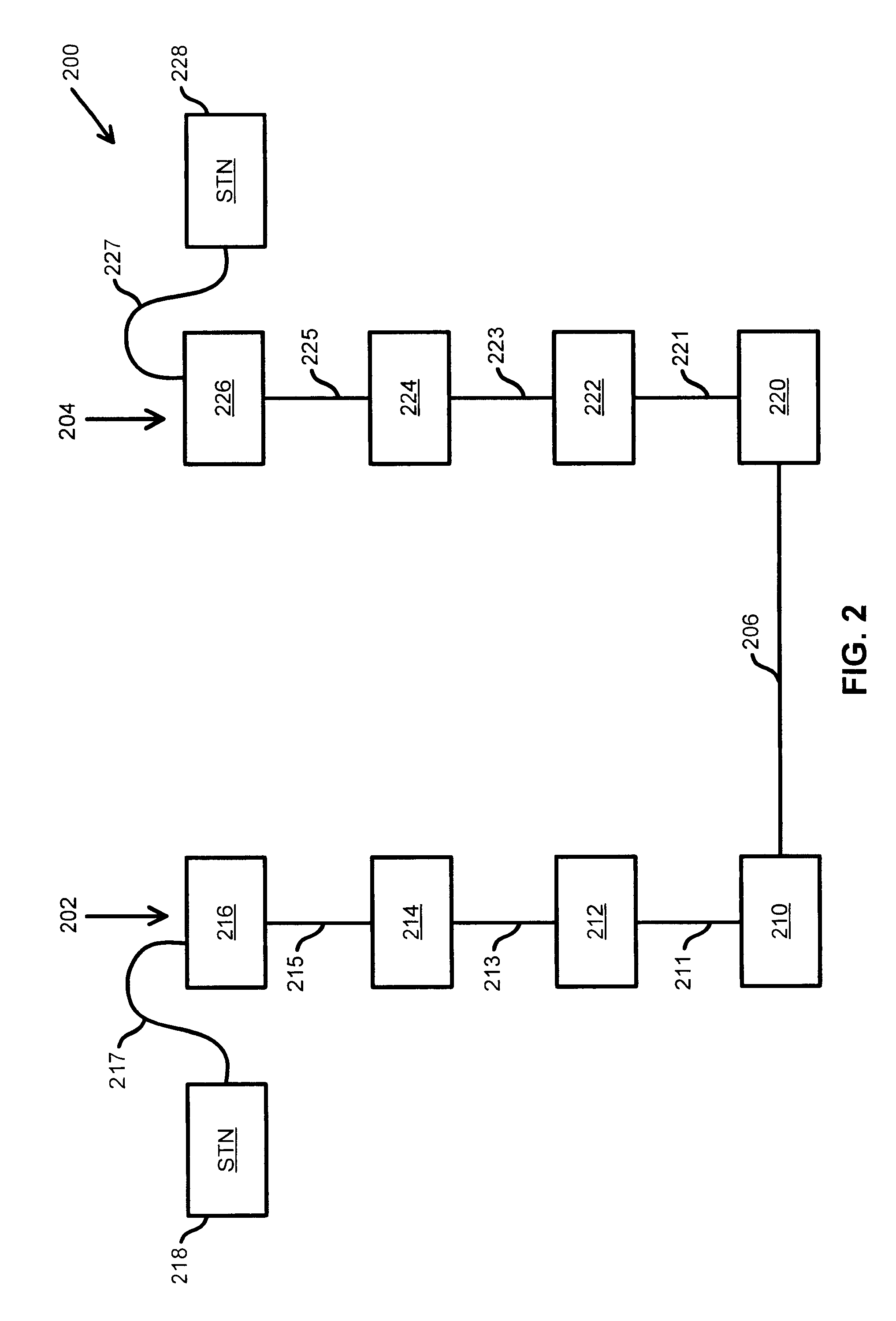
FIG. 2 depicts a block diagram of a Class II Fast Ethernet incorporating two cascaded stacked...


PUM


Abstract

Provided is a synchronous stack bus repeater system for a computer network. The system includes a plurality of stacked repeaters, a stack bus linking the repeaters, and a single clock to which the plurality of repeaters is synchronized. The synchronization of the stack bus eliminates several time-consuming communications required between devices operating with different clocks on an asynchronous bus and makes it possible to satisfy the 46 bit time repeater maximum latency required of a Class II repeater according to the IEEE 802.3 standard.

Description

BACKGROUND OF THE INVENTIONThe present invention relates generally to network computing. In particular the present invention relates to methods and apparatuses for synchronizing a stack bus on a Fast Ethernet repeater stack.The growth of local-area networks (LANs) has been driven by the introduction of Ethernet technology as well as the availability of powerful, affordable personal computers and workstations. As a result, applications that once were possible only on mainframe computers are now running on LANs. Network speed and availability are critical requirements. However, existing applications and a new generation of multimedia, groupware, imaging, and database products can tax a network running at Ethernet's traditional speed of 10 megabits per second (Mbps). Moreover, with more applications requiring faster LAN speeds for acceptable performance, network managers increasingly find that high-performance computation platforms and mission-critical applications can overwhelm a 10 M...

Claims


Application Information

Patent Timeline
Patent Type & Authority Patents(United States)
IPC IPC(8): H04L12/40H04J3/06
CPCH04L12/40H04J3/06
Inventor VOLOSHIN, MOSHECAVARO, MARK D.
Owner CISCO TECH INC
Why Eureka
Try Eureka