
Method for measuring the dose distribution in a computed tomography apparatus

a computed tomography and dose distribution technology, applied in the direction of instruments, diaphragms, radiation diagnostic devices, etc., can solve the problem of no longer being required for error-prone evaluation of the blackening of the film, and achieve the effect of less outlay and less susceptible to error

Inactive Publication Date: 2005-02-01
SIEMENS HEALTHCARE GMBH
View PDF5 Cites 2 Cited by
  • Summary
  • Abstract
  • Description
  • Claims
  • Application Information

AI Technical Summary

Benefits of technology

The present invention provides a method for measuring the dose distribution in a computed tomography apparatus that is less expensive and less prone to errors than conventional techniques.

Problems solved by technology

The technical problem addressed in this patent is the need for a more efficient and accurate method of quality assurance in computed tomography apparatuses. The conventional method of using X-ray film for quality assurance is complicated and requires manual evaluation, leading to errors. The patent proposes a method to acquire the dose distribution of the X-ray bundle emitted by the X-ray tube and use it to correct the image data for inhomogeneous distribution and detector sensitivity.

Method used


Image

  • Method for measuring the dose distribution in a computed tomography apparatus
  • Method for measuring the dose distribution in a computed tomography apparatus
  • Method for measuring the dose distribution in a computed tomography apparatus

Examples


Embodiment Construction

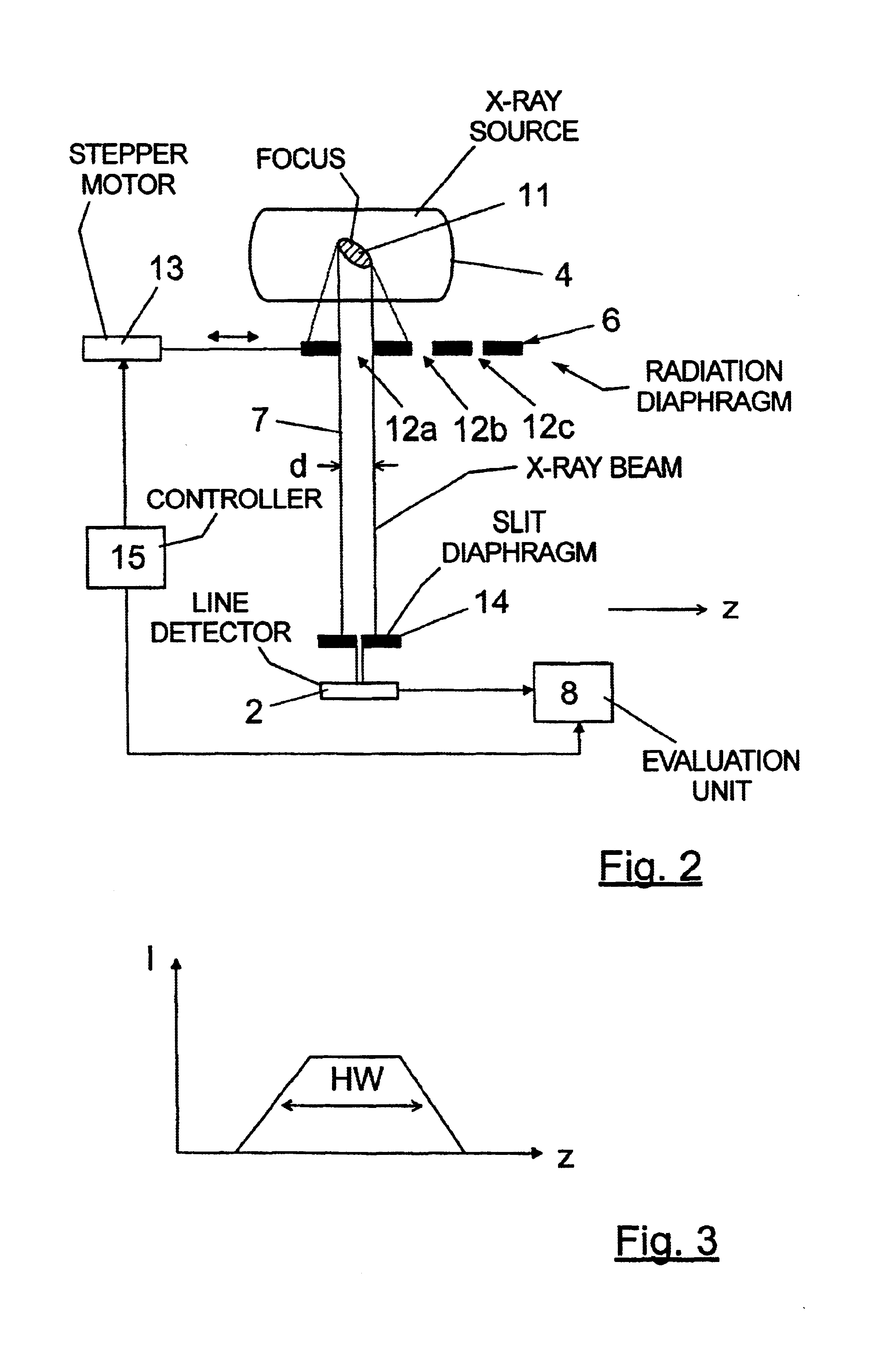
[0021]FIG. 2 is a simplified illustration of the limitation of the fan-shaped X-ray bundle by a radiation diaphragm at the tube side as well as the slit diaphragm arranged at the detector side for implementing the inventive method.

[0022]FIG. 3 is an example of the dose distribution measured with the inventive method for a setting of the radiation diaphragm.

[0023]FIG. 4 shows the illustration of FIG. 2 with an alternative version of the radiation diaphragm.

DESCRIPTION OF THE PREFERRED EMBODIMENTS

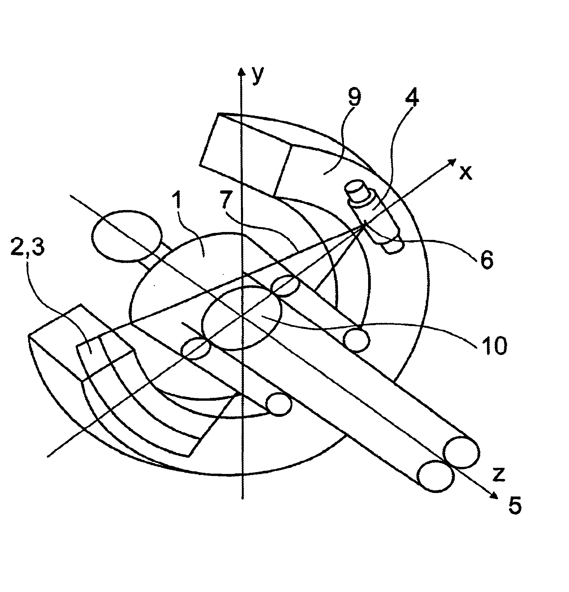
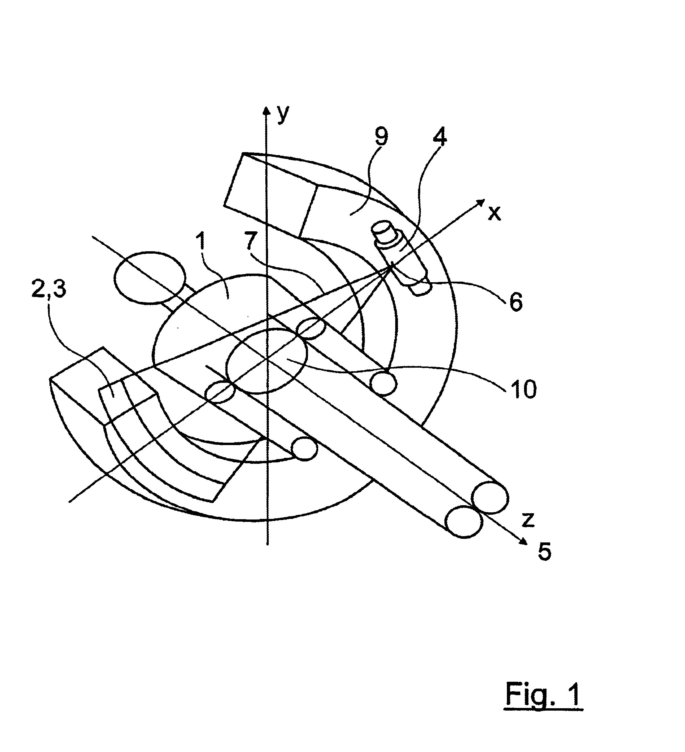
[0024]In a schematic view, FIG. 1 shows a part of a computed tomography system for illustrating the geometrical relationships in the acquisition of measured data. The computed tomography system has an X-ray source in the form of an X-ray tube 4 that emits a fan-shaped X-ray bundle 7 in the direction of a detector bank having a line 2 composed of detector elements 3 (only a few of which are shown in FIG. 1). The X-ray tube 4 as well as the detector elements 3 are arranged at a gantry 9 that ca...


PUM


Abstract

In a method for measuring the dose distribution in a computed tomography apparatus, wherein the dose distribution of an X-ray beam emitted by an X-ray tube with a thickness prescribed by a radiation diaphragm is acquired in the thickness direction for at least one setting of the radiation diaphragm, the dose distribution is acquired in the thickness direction with detector elements of a detector line of the computed tomography system in front of which a slit diaphragm is attached, while adjusting the radiation diaphragm so that each possible setting is set. The dose distribution can be acquired in automated fashion and without manual evaluation that is susceptible to error.

Description


Claims


Application Information

Patent Timeline
Owner SIEMENS HEALTHCARE GMBH
Learn More