
Camera having lens barrier

Inactive Publication Date: 2005-02-01
ASAHI KOGAKU KOGYO KK
View PDF67 Cites 3 Cited by
  • Summary
  • Abstract
  • Description
  • Claims
  • Application Information

AI Technical Summary

Benefits of technology

The present invention provides an inexpensive compact camera in which the opening state of the lens barrier can be certainly detected.
The camera can include a zoom lens camera, and the sub-lens group shifting device can move the front lens support frame between the mutually close position and the mutually distant position with respect to the rear lens support frame, in accordance with the movement of the zoom lens between a telephoto side photographing position and a wide-angle side photographing position.
The camera can further include a focus drive mechanism which moves the front lens support frame together with the rear lens support frame to an in-focus position in the optical axis direction, in accordance with an object distance. The barrier detection device causes the focus drive mechanism to integrally move the front and rear lens support frames together in the optical axis direction, independently of a focusing operation, to detect the opening state of the lens barrier in accordance with the amount of movement of the front end rear lens support frames.

Problems solved by technology

However, in a camera in which a photographing optical system is independent from an object viewing optical system, even if, upon photographing, the barrier is not completely opened due to some reason, there is a chance that a photographer (operator) takes a picture without noticing the incomplete opening of the lens barrier, because the incomplete opening of the lens barrier has no influence on an object image viewed by the photographer through the viewing optical system.

Method used


Image

  • Camera having lens barrier
  • Camera having lens barrier
  • Camera having lens barrier

Examples


Embodiment Construction

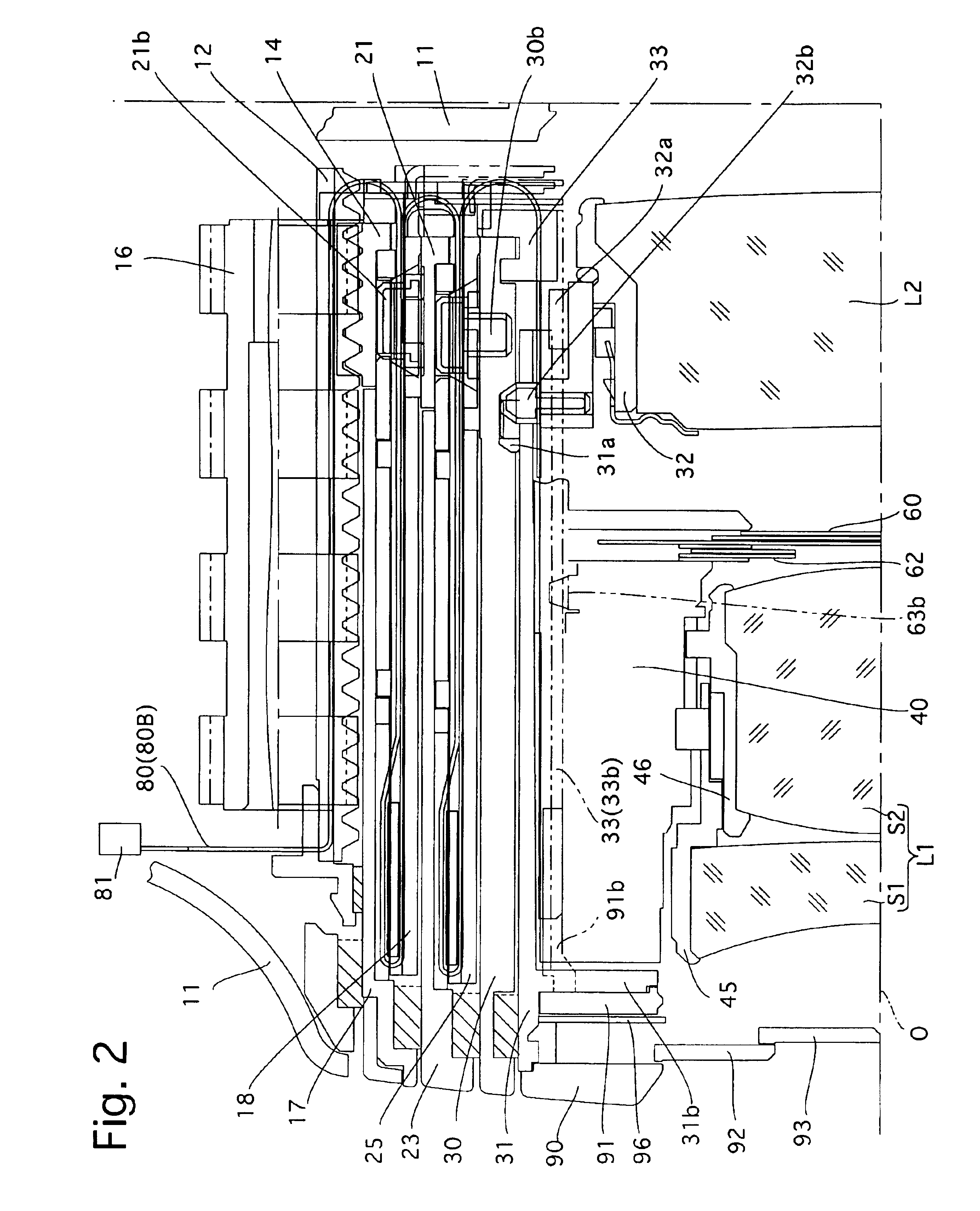
The following embodiments are addressed to a zoom lens camera having a lens barrier. The structure of the zoom lens barrel in a zoom lens camera will be discussed first and the features of the present invention including a lens barrier mechanism will be discussed thereafter.

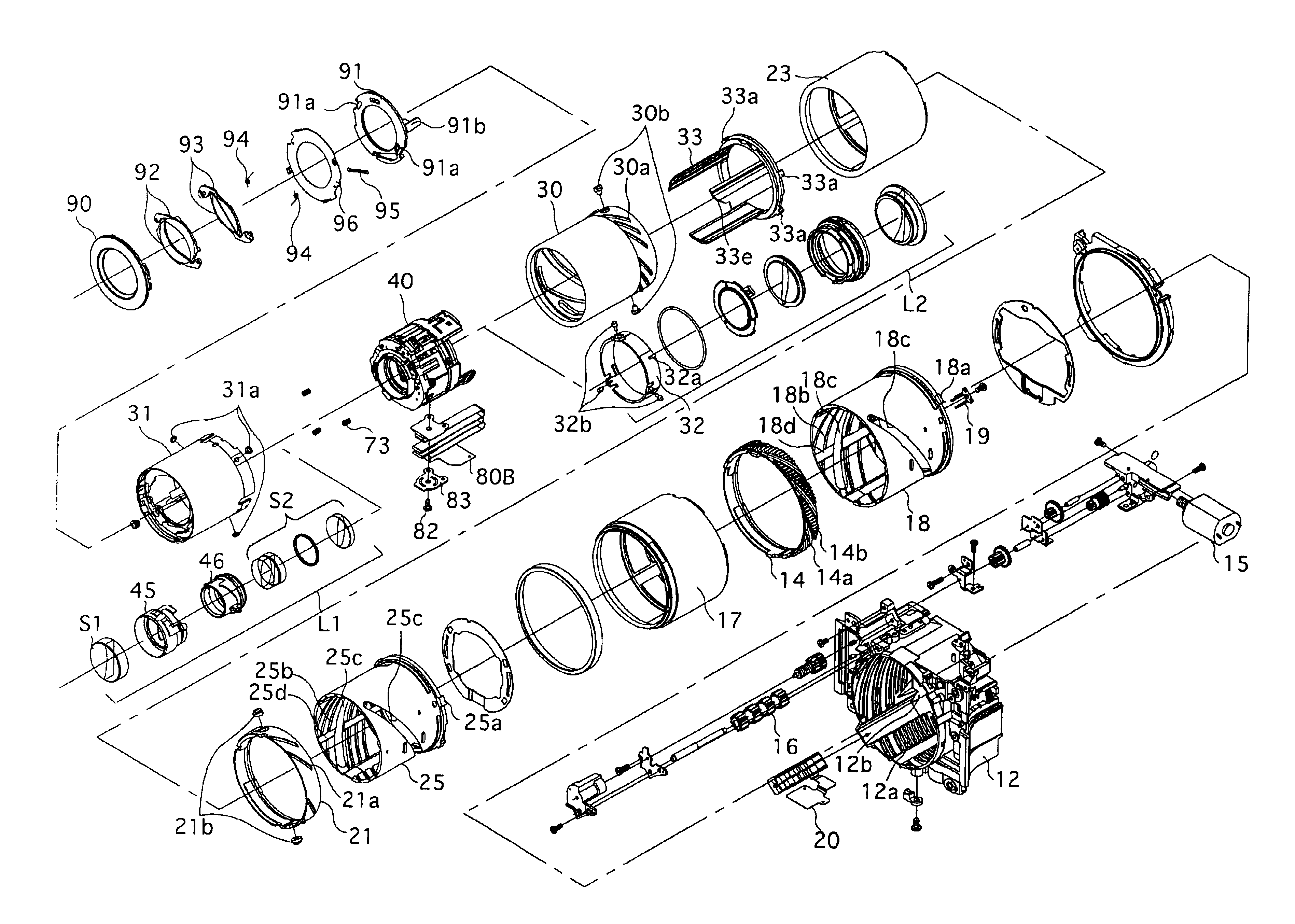
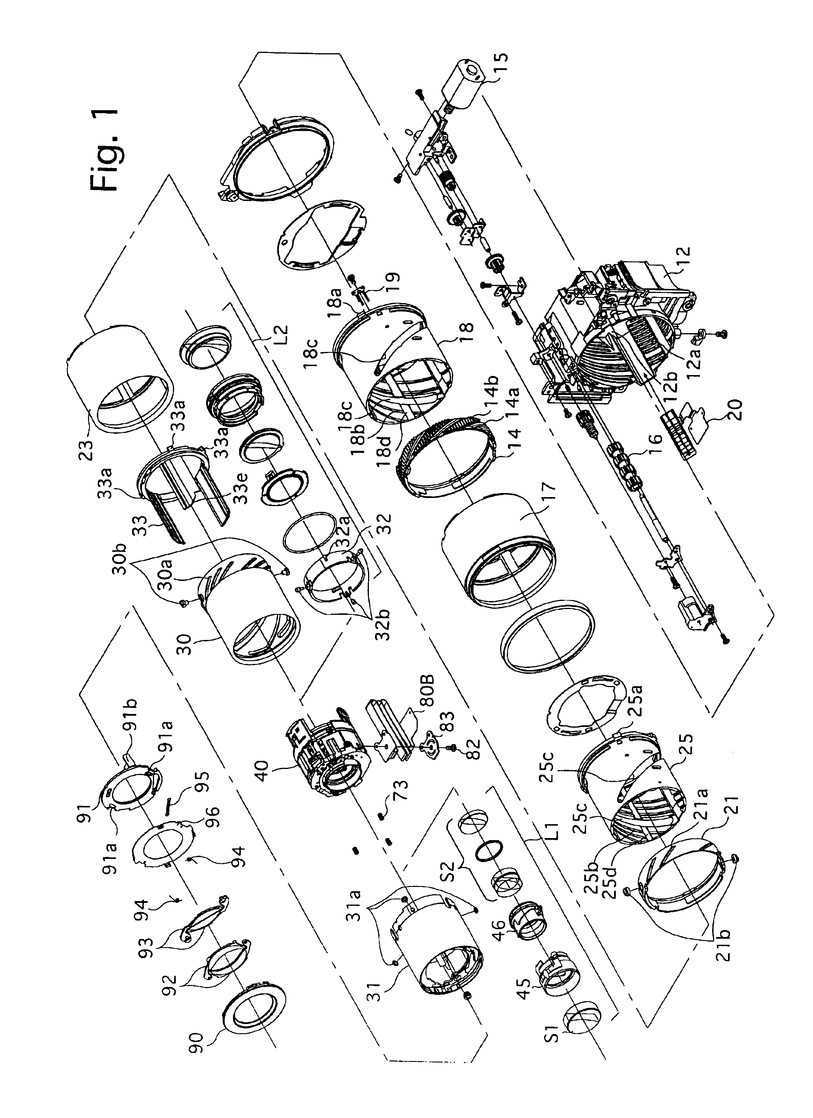
As shown in FIG. 1, a stationary barrel 12 secured to a camera body 11 is provided on its inner peripheral surface with a female helicoid 12a which is screw-engaged with a male helicoid 14a formed on an outer peripheral surface of a first helicoid ring 14. A pinion 16 which is rotated by a zooming motor 15 is provided outside the stationary barrel 12. The pinion 16 is in mesh with a gear 14b formed on the outer peripheral surface of the first helicoid ring 14 via a cut-out portion of the male helicoid 14a. The gear 14b is inclined in the same direction as the lead of the male helicoid 14a. The first helicoid ring 14 is connected at the front end thereof to a first outer barrel 17. Consequently, when the first hel...


PUM


Abstract

A camera includes a lens support frame which supports a photographing lens group; an outer lens barrel which is provided on the front end thereof with a photographing aperture through which the lens support frame is moved; a lens barrier mechanism which opens and closes the photographing aperture of the outer lens barrel; a lens drive mechanism which moves the lens support frame in the outer lens barrel between a forward movement extremity in which the front end of the lens support frame is located in front of the photographing opening in an optical axis direction, and a rearward movement extremity in which the front end of the lens support frame is located behind the photographing aperture; and a barrier detection device for detecting the opening state of the lens barrier mechanism, based on an amount of movement of the lens support frame in the optical axis direction via the lens drive mechanism.

Description

BACKGROUND OF THE INVENTION1. Field of the InventionThe present invention relates to a camera having a lens barrier.2. Description of the Related ArtIn a known compact camera, etc., a front portion of a lens is automatically closed by a lens barrier to protect the lens when the camera is not used. However, in a camera in which a photographing optical system is independent from an object viewing optical system, even if, upon photographing, the barrier is not completely opened due to some reason, there is a chance that a photographer (operator) takes a picture without noticing the incomplete opening of the lens barrier, because the incomplete opening of the lens barrier has no influence on an object image viewed by the photographer through the viewing optical system.SUMMARY OF THE INVENTIONThe present invention provides an inexpensive compact camera in which the opening state of the lens barrier can be certainly detected.For example, a camera is provided, including a lens support fram...

Claims


Application Information

Patent Timeline
IPC IPC(8): G03B17/00G02B7/02G02B7/08G02B7/09G02B7/10G03B11/04G03B17/18G03B17/20
CPCG03B17/00
Inventor NOMURA, HIROSHISASAKI, TAKAMITSUISHIZUKA, KAZUNORITAKASHIMA, MAIKO
Owner ASAHI KOGAKU KOGYO KK
Learn More