

Berth system, especially for means of transportation
a technology for berths and vehicles, applied in the direction of seating furniture, application, cosmonautic components, etc., can solve the problems of half the berth length available, inability to choose the height of the sitting room independently, and not being suitable for passengers' presen
- Summary
- Abstract
- Description
- Claims
- Application Information
AI Technical Summary
Benefits of technology
Problems solved by technology
Method used
Image

Examples
Embodiment Construction
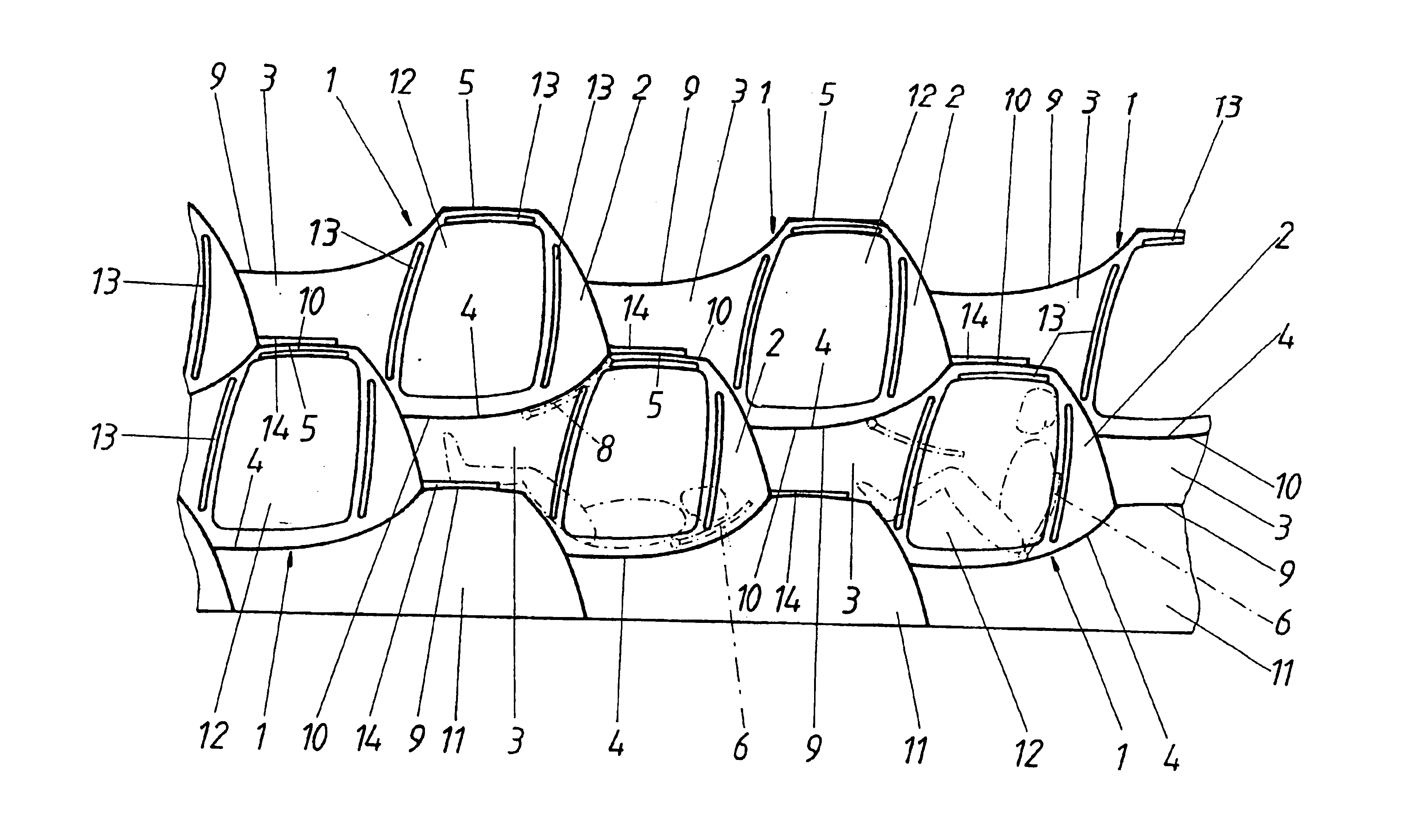
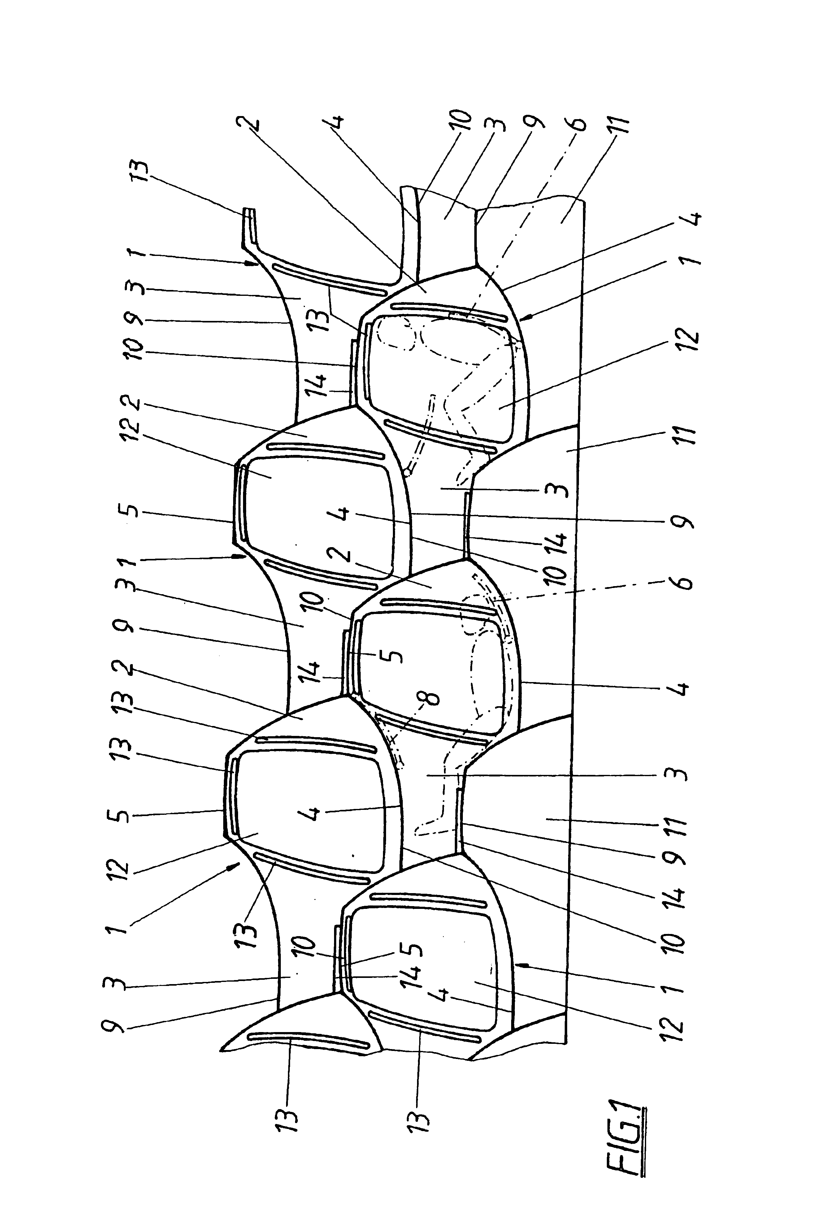
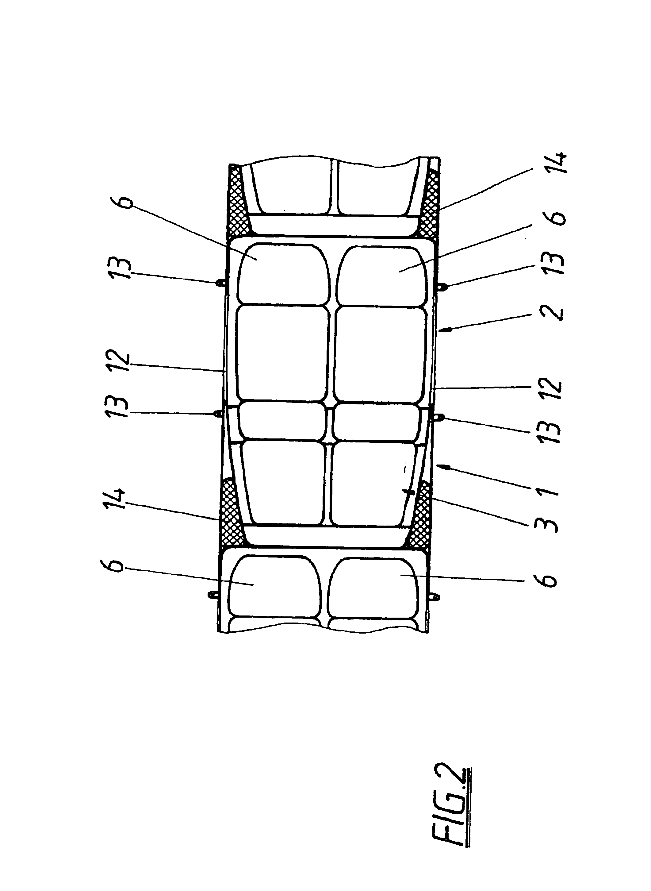
The invention is thus based on the object of configuring a berth arrangement of the kind mentioned above with simple constructional means in such a way that a uniform alignment of all single berths is enabled under an advantageous utilization of space and the sitting room height can be chosen independent from the foot room height in order to provide both advantageous lying as well as sitting conditions for the user.
The invention achieves this object in such a way that the respective ceilings and floors of the sitting rooms correspond to the negative shapes of the floors and ceilings of the foot space.
Since as a result of this measure the foot and sitting rooms of the single berths arranged above each other come to lie alternatingly one on top of the other, the sitting and foot rooms situated alternatingly above each other determine the overall height of the berth arrangement. The sitting room height and the foot room height can be determined independently from each other. This provi...
PUM
 Abstract
Description
Claims
Application Information