Partition panel with modular appliance mounting arrangement
What is AI technical title?
AI technical title is built by Patsnap AI team. It summarizes the technical point description of the patent document.
a technology of partition panel and modular appliance, which is applied in the direction of machine supports, service system furniture, mechanical equipment, etc., can solve the problems of large overall size or “footprint” of the workspace for a given user, insufficient flexibility of existing furniture systems, and difficulty in adjusting the position of hang-on furniture units
Inactive Publication Date: 2005-02-08
STEELCASE INC
View PDF204 Cites 103 Cited by
Summary
Abstract
Description
Claims
Application Information
AI Technical Summary
This helps you quickly interpret patents by identifying the three key elements:
Problems solved by technology
Method used
Benefits of technology
Benefits of technology
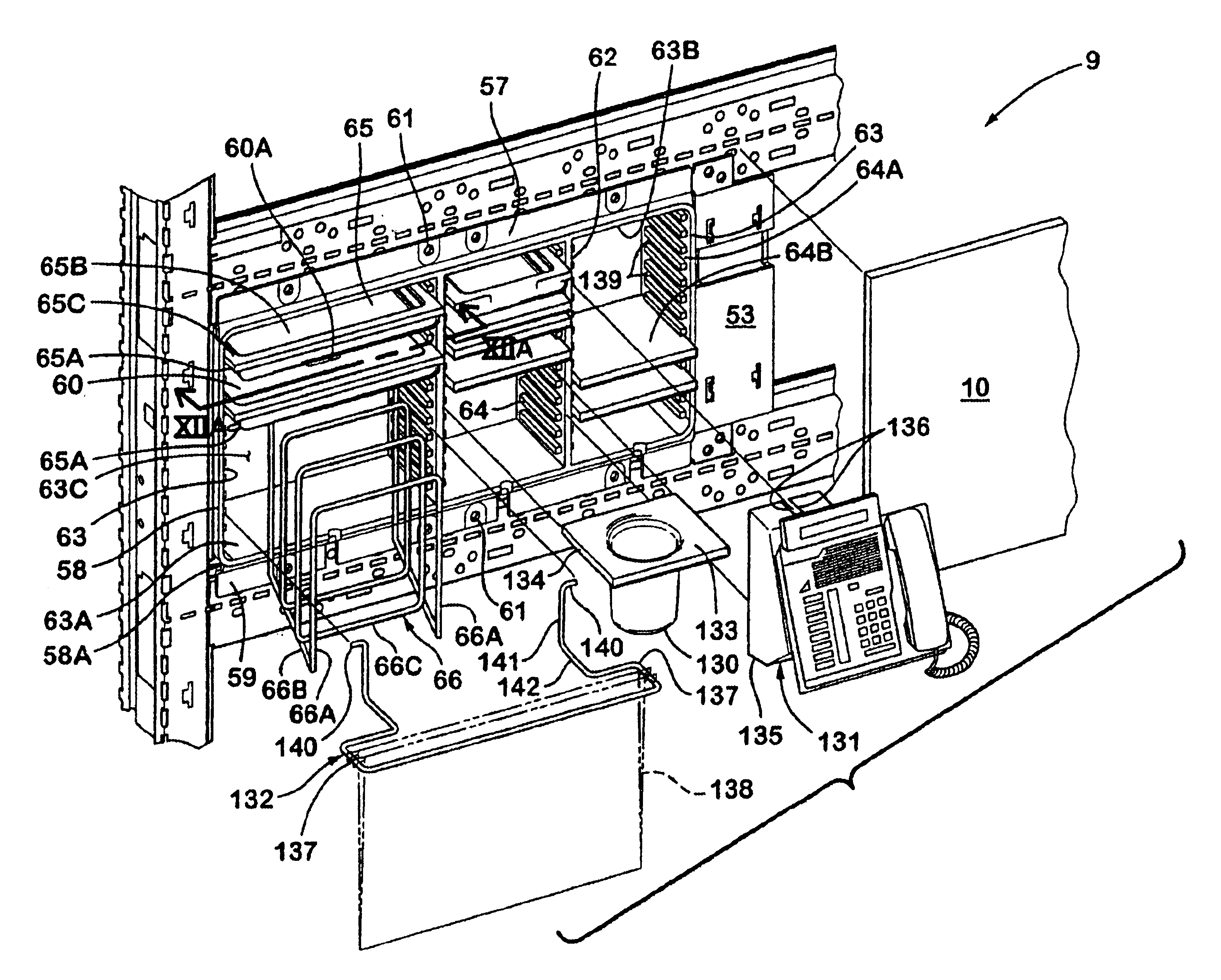
One aspect of the present invention is a freestanding partition panel for dividing a floor space. The partition panel includes a rigid partition frame having horizontally spaced apart vertical side frame members and vertically spaced apart first and second horizontal frame members extending between the vertical side frame members to form a generally quadrilateral vertically enlarged opening through the frame, and defining an open space within the panel. The partition panel includes at least one intermediate horizontal cross member extending across the vertically enlarged opening and defining an upper opening through the frame above the intermediate horizontal cross member, and defining a lower opening through the frame below the intermediate horizontal cross member. The intermediate cross member and at least a selected one of the first and second horizontal frame members include a plurality of horizontally spaced apart attachment locations defining a plurality of discrete, serially adjacent mounting spaces in a selected one of the upper and lower openings through the frames within the open space. The partition panel further includes a utility unit connectable to selected ones of the attachment locations of the intermediate horizontal cross member and the selected one of the first and second horizontal members, such that the utility unit can be mounted in a selected one of the mounting spaces. The utility unit has a side edge spaced apart from a selected one of the vertical side frame members. The partition panel further includes a first cover panel secured to the partition frame and extending horizontally between the side edge of the utility unit and the selected vertical side frame member. The first cover panel is connected to the intermediate horizontal cross member and extends vertically between the intermediate horizontal cross member and the selected one of the first and second members. A second cover panel is secured to the partition frame, and extends horizontally between the vertical side frame members. The second cover panel extends vertically between the intermediate horizontal cross member and the other of the selected one of the first and second members.
Problems solved by technology
Both of these types of modular furniture systems, as well as others, have been widely received due largely to their ability to be readily reconfigured and / or moved to a new site, since they are not part of a permanent leasehold improvement.
However, existing furniture systems may not provide sufficient flexibility to permit the location of the hang-on furniture units to be readily adjusted.
Furthermore, positioning of the cover panels on existing systems may be problematic.
In general, the worksurfaces must be relatively large to support such equipment, such that the overall size or “footprint” of the workspace for a given user will be quite large.
The relatively large footprint requires more floor space, leading to more cost per user.
Method used
Image
Click on the blue label to locate the original text in one second.
Reading with bidirectional positioning of images and text.
Examples
Embodiment Construction
The present application is related to co-pending patent application Ser. No. 10 / 077,553 entitled PANEL SYSTEM, filed on even date herewith, the entire contents of which are hereby incorporated by reference.
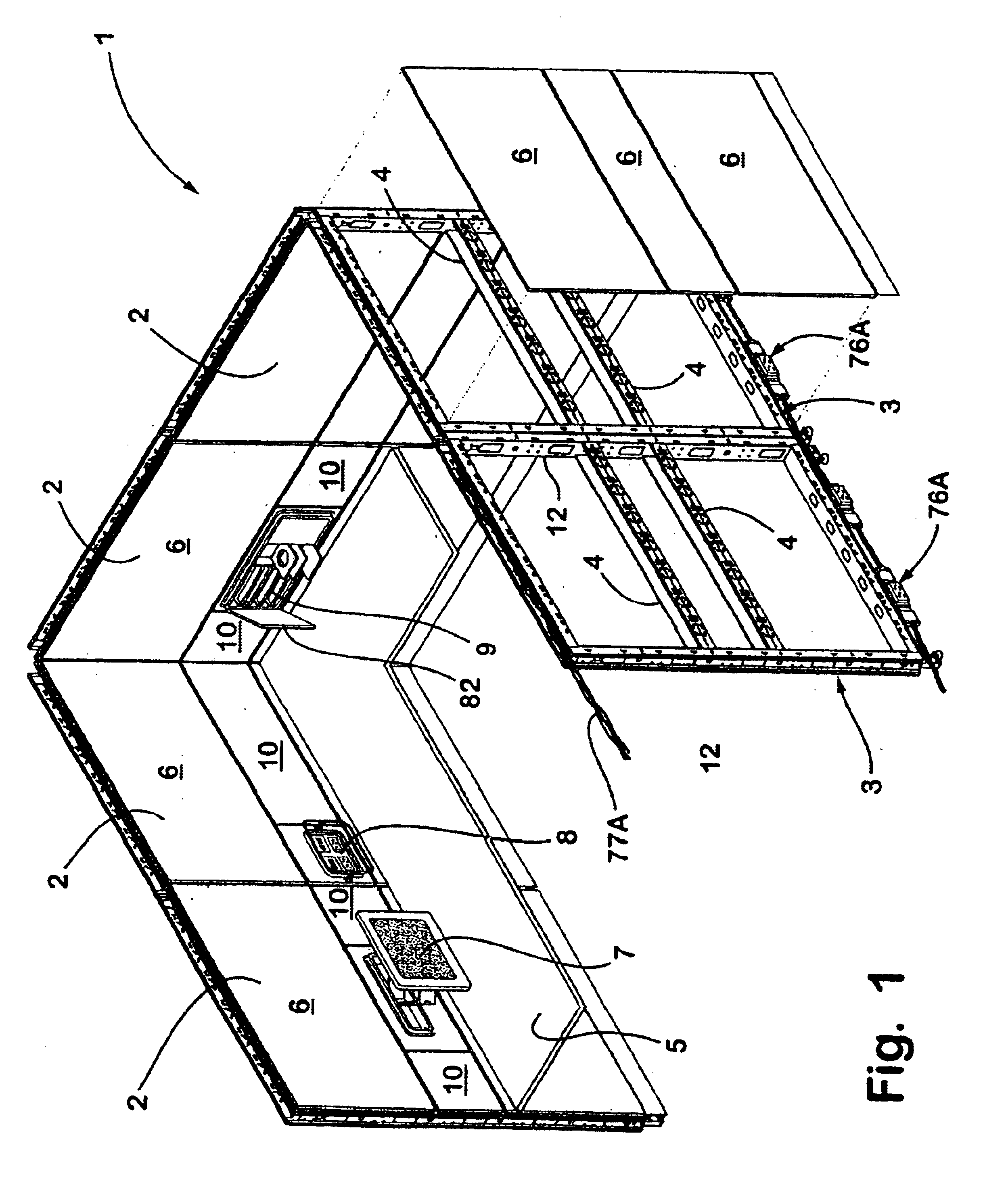
For purposes of description herein, the terms “upper,”“lower,”“right,”“left,”“rear,”“front,”“vertical,”“horizontal,” and derivatives thereof shall relate to the invention as oriented in FIG. 1. However, it is to be understood that the invention may assume various alternative orientations and step sequences, except where expressly specified to the contrary. It is also to be understood that the specific devices and processes illustrated in the attached drawings and described in the following specification are simply exemplary embodiments of the inventive concepts defined in the appended claims. Hence, specific dimensions and other physical characteristics relating to the embodiments disclosed herein are not to be considered as limiting, unless the claims expressly state otherwise.
Th...
PUM
Abstract
A freestanding partition panel for dividing a floor space includes a rigid partition frame having vertical side frame members and first and second horizontal frame members extending between the vertical side frame members to form a vertically enlarged opening through the frame, and an open space within the panel. At least one intermediate horizontal cross member extends across the vertically enlarged opening and defines upper and lower openings through the frame. The intermediate cross member and at least a selected one of the first and second horizontal frame members include a plurality of horizontally spaced apart attachment locations defining a plurality of discrete, serially adjacent mounting spaces. The partition panel further includes a utility unit that is mountable in a selected one of the mounting spaces. The partition panel further includes a first cover panel secured to the partition frame and extending horizontally between the side edge of the utility unit and the selected vertical side frame member. The first cover panel is connected to the intermediate horizontal cross member and extends vertically between the intermediate horizontal cross member and the selected one of the first and second members. A second cover panel is secured to the partition frame, and extends horizontally between the vertical side frame members. The second cover panel extends vertically between the intermediate horizontal cross member and the other of the selected one of the first and second horizontal members.
Description
BACKGROUND OF THE INVENTIONThe present invention relates to open office plans and the like.The efficient use of building floor space is an ever-growing concern, particularly as building costs continue to escalate. Open office plans have been developed to reduce overall officing costs, and generally incorporate large, open floor spaces in buildings that are equipped with modular furniture systems which are readily reconfigurable to accommodate the ever-changing needs of a specific user, as well as the divergent requirements of different tenants. One arrangement commonly used for furnishing open plans includes movable partition panels are detachably interconnected to partition off the open spaces into individual workstation and / or offices. Such partition panels are configured to receive hang-on furniture units, such as worksurfaces, overhead cabinets, shelves, etc., and are generally known in the office furniture industry as “systems furniture”. Another arrangement for dividing and / or...
Claims
Application Information
Patent Timeline
Application Date:The date an application was filed.
Publication Date:The date a patent or application was officially published.
First Publication Date:The earliest publication date of a patent with the same application number.
Issue Date:Publication date of the patent grant document.
PCT Entry Date:The Entry date of PCT National Phase.
Estimated Expiry Date:The statutory expiry date of a patent right according to the Patent Law, and it is the longest term of protection that the patent right can achieve without the termination of the patent right due to other reasons(Term extension factor has been taken into account ).
Invalid Date:Actual expiry date is based on effective date or publication date of legal transaction data of invalid patent.
InventorMACGREGOR, BRUCE G.NOVOA, JUAN CARLOS BRUCECHENG, LARRYCRUSE, II, ENERGYEICH, THOMAS B.FOURT, JESSE A.GRESHAM, DAVID M.GRISHAVER, ALEX T.HEI, JOSEPH LISHINGINOUYE, MATTHEW D.KUCHENBECKER, KATHERINE J.LUDWIG, JAMES N.NEWMAN, SVEN D.PELMAN, TODD A.SALAMINI, ALEXEYSCHULZ, FRANZ NIKLAUSTARBELL, BENJAMIN J. V.WHITMAN, SCOTT A.WEBSTER, DAVID M.

