Thermal-type flow meter with bypass passage

a flow meter and bypass passage technology, applied in the field of flow measurement sensors, can solve the problems of increasing pulsation becomes very complicated, and the amount of reverse flow tends to increase, so as to reduce the measurement error, increase the reliability, and ensure the effect of reliability

Inactive Publication Date: 2005-02-08
HITACHI ASTEMO LTD
View PDF9 Cites 22 Cited by
  • Summary
  • Abstract
  • Description
  • Claims
  • Application Information

AI Technical Summary

Benefits of technology

The main object of the present invention is to provide a flow measurement sensor in which pulsation detected by the flow measurement element is not affected by pulsation generated on the back side of the support member, thereby providing the accurate measurement when pulsation flow and reverse flow occur.
Furthermore, another characteristic of the present invention is that said flow measurement element or said support member is disposed such that the flow measurement sensor mounting side is inclined so as to face the forward flow in the main passage in which the flow measurement sensor is positioned. This arrangement makes it possible to provide a flow measurement sensor which has, in addition to the aforementioned effect, weak flow noise under the steady flow conditions.

Problems solved by technology

However, in an engine which conducts complex controls, such as a continuous variable Valve Timing mechanism or the like, so as to respond to regulation of exhaust gas and fuel saving, pulsation flow and reverse flow occur at high engine speed and the amount of reverse flow tends to increase.
Accordingly, once pulsation deviation is generated between the flow measurement element mounting surface and the other surface where the flow measurement element is not mounted, the pulsation becomes very complicated and sufficient measurement accuracy cannot be obtained.
Further, the flow-dividing ratio at the time the support member divides the flow into face side flow and back side flow easily changes depending on the conditions of the steady flow or pulsation flow, thereby causing the flow rate error.
However, in this structure, moisture easily adheres to the thin film member of the flow measurement element, and once moisture adheres, a problem arises because accurate flow measurement becomes impossible while the moisture is present.
Furthermore, when condensation, occurs in the bypass passage, relatively large droplets of water easily adhere to the flow measurement element.
If a water droplet adheres, the affected area will not be heated to more than 100° C. until the water droplet is removed; however, the feedback circuit tries to adjust the control so that the value becomes Th, thereby causing overcurrent.
If a boiling phenomenon occurs in the water droplet casing air bubbles to generate, the bubble generating area (area which comes in contact with air) is heated up to a very high temperature due to the overcurrent, which may cause damage.
However, if the air filter of the air cleaner is removed or particles which have passed through the air filter accumulate by crosslinking a liquid, such as oil or water, present in an intake pipe, there is a possibility that particles which may destroy the thin film member of the flow measurement element may reach and adhere to the surface of the flow measurement element.
As described above, it is difficult for the prior art to simultaneously and adequately satisfy the functions: the reduction of the measurement error when intake air flow pulsates, prevention of measurement accuracy from decreasing due to the presence of water droplets, and prevention of dust present in intake air from impinging on the flow measurement element.

Method used


Image

  • Thermal-type flow meter with bypass passage
  • Thermal-type flow meter with bypass passage
  • Thermal-type flow meter with bypass passage

Examples


first embodiment

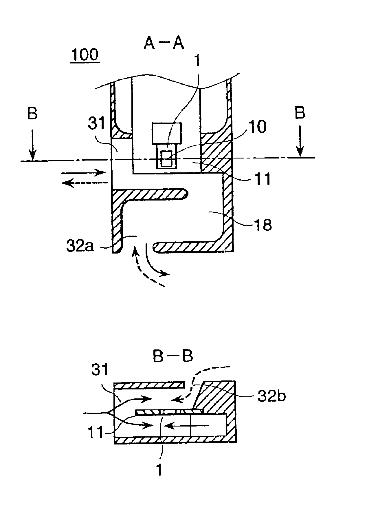
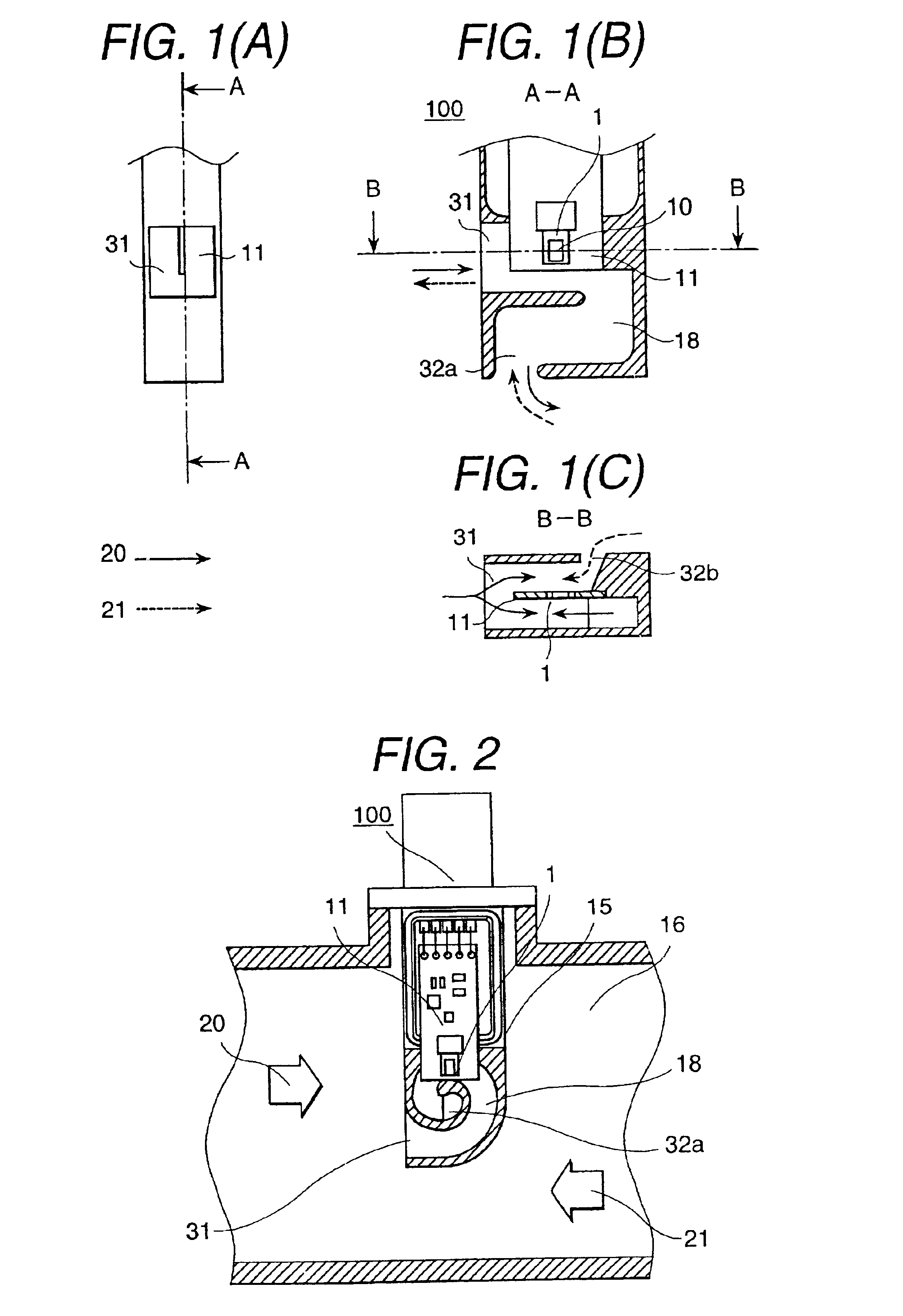
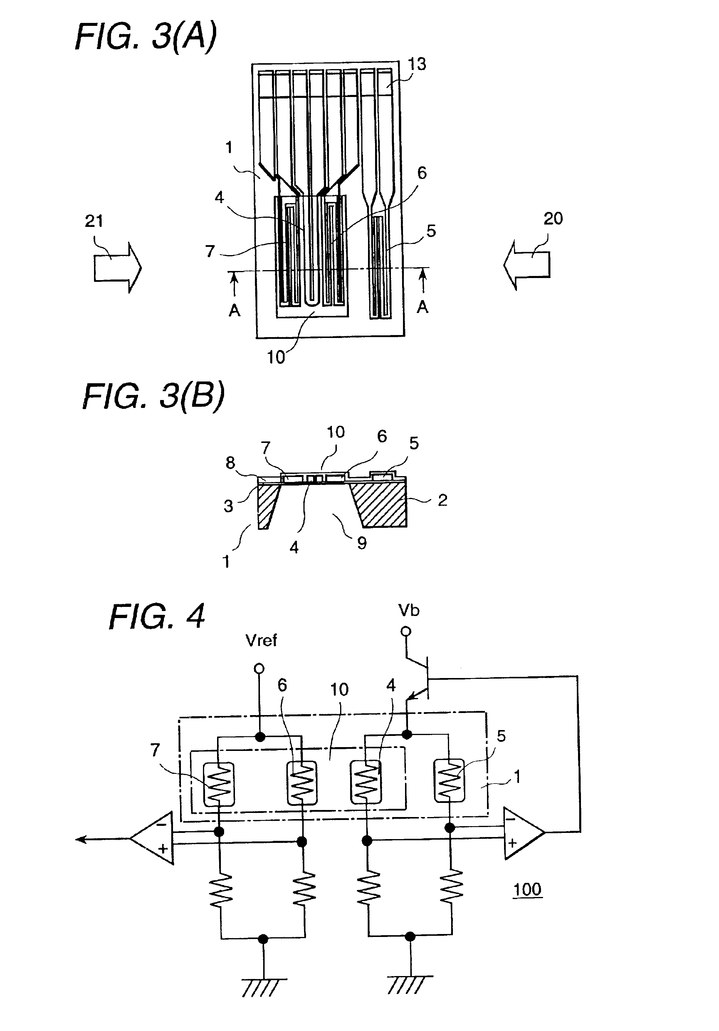
A flow measurement sensor 100 of a first embodiment comprises a flow measurement element 1 which has a heater resistance pattern, i.e. thin film structure 10, on one side of a plate-shaped support member 11, and a bypass passage 18 in which the flow measurement element 1 is disposed. The flow measurement element 1 is fixed to a concaved portion (see FIG. 11) provided in one side of the support member 11 so that the surface becomes slightly, for example, approximately 10 μm lower than the flat surface of the support member 11 by epoxy or silicon adhesive. As understood from the top view, the support member 11 is located near the center of the bypass passage 18 and divides the bypass passage 18 into a first passage through which fluid flows along the support member surface to which the flow measurement element is not mounted, and a second passage through which fluid flows along the surface of the flow measurement element. The bypass passage 18 comprises an inlet 31, a first outlet 32a...

third embodiment

However, according to the present invention, it is possible that reverse flow is easily guided to the back side of the support member 11 without increasing the reverse flow on the surface of the flow measurement element, so that air flow on the surface of the flow measurement element 1 can be increased by being dragged by the reverse flow. This technology makes highly accurate measurement possible in the entire area regardless of the pulsation amplitude being small or large and at any engine speed.

Next, FIG. 8 shows sectional views and a top view of a flow measurement sensor which is a fourth embodiment of the present invention. The fourth embodiment is an altered example of the third embodiment. In this embodiment, a protrusion 33 which extends in the direction perpendicular to the axial direction of the main passage 16 is provided on the upstream side of the second outlet 32b so as to be easily applied dynamic pressure of reverse flow 21, thereby the reverse flow 21 is easily guid...

fifth embodiment

Therefore, in order to provide a flow measurement sensor 100 which has long-lasting reliability, it is necessary to structure the sensor such that air reaches the surface of the flow measurement element 1 but dust and moisture are kept away. As a means to solve this problem, a bypass passage 18, shown in FIG. 9, which is the present invention is effective. In this embodiment, the radius of the bypass passage 18 gradually becomes small in the direction of forward flow in the bypass passage. The flow measurement element is disposed inside in the radial direction from the outer-wall surface of the bypass passage. Further, a first outlet 32a faces the direction perpendicular to the axial direction of the main passage 16. A first outlet 32a opens in the direction perpendicular to the axial direction of the main passage 16. Further, a second outlet 32b opens in the axial direction of the main passage 16, away from the first outlet 32a.

The bypass passage 18 of this embodiment generates a ...


PUM


Abstract

A flow measurement sensor accurately outputs signals even when pulsation flow is generated at high engine speed and also when pulsation flow accompanying reverse flow is generated. The flow measurement sensor has a flow measurement element which has a heater resistance pattern on one side of a plate-shaped member, and a bypass passage in which the flow measurement element is disposed, a first outlet through which fluid flowing along the surface of the flow measurement element flows out, and a second outlet through which fluid flowing along the back side of the flow measurement element flows out. The second outlet is positioned at a different location from the first outlet.

Description

BACKGROUND OF THE INVENTION1. Field of the InventionThe present invention relates to a flow measurement sensor for measuring a flow rate by using a heater resistance(=heating resistor), for example, a flow measurement sensor which is suitable for measuring the intake air flow rate of an internal combustion engine to control fuel supply.2. Prior ArtConventionally, as a flow measurement sensor which is installed in an intake air flow passage of an internal combustion engine, such as an automobile or the like, to measure the intake air flow rate, thermal-type flow measurement sensors have been main stream because they can directly detect the mass flow rate. Of such thermal-type flow measurement sensors, a flow measurement sensor which is produced on a semiconductor substrate, such as silicon (Si) or the like, by using semiconductor micro processing technology has been popular because it is relatively economical due to easy mass production, small, and can be driven by low power.As such ...

Claims


Application Information

Patent Timeline
Patent Type & Authority Patents(United States)
IPC IPC(8): F02D41/18G01F1/684G01F1/72G01F5/00F02D35/00G01F1/68
CPCF02D41/187G01F5/00G01F1/72G01F1/6842F02D2041/2072
Inventor NAKADA, KEIICHIWATANABE, IZUMIHORIE, JUNICHIUEDA, KEI
Owner HITACHI ASTEMO LTD
Why Eureka
Try Eureka