Burner with piloting ports

a burner and piloting technology, applied in the field of cooking appliances, can solve the problems of limited range of gas flow rate, non-standard control of stability, and limited flame kernel, so as to improve the turn down ratio and cooking efficiency, and improve the stability of flame kernels

Inactive Publication Date: 2005-02-08
BSH HOME APPLIANCES CORP
View PDF49 Cites 47 Cited by
  • Summary
  • Abstract
  • Description
  • Claims
  • Application Information

AI Technical Summary

Benefits of technology

The present invention overcomes the above mentioned disadvantages by providing a method for improving turn down ratio in a cooking appliance, as well as providing burner constructions and installations that generate flame kernel stability, through piloting. As used in this application, the term piloting is used to refer to contributions to control of the formation and the positioning of flame kernels as they emanate from the burner port outlets.
In general, a burner body has at least one burner port in communication with the primary air passage and having a defined alignment with respect to an adjacent structure that guides the formation of a flame kernel at the outlet of the port. The adjacent structure may be on the body, for example, a burner cap, on a separate element or be created by the orientation of an adjacent burner port or ports. For example, ports aligned for overlapping kernel generation at the outlets of the adjacent ports, or a port having an axis aligned at a converging angle with respect to an axis of the adjacent port outlet may provide interport piloting. In addition, adjacent ports may be positioned within an interport piloting distance of the flame kernel or aligned to provide an overlapping kernel generation at the outlets of the ports. Furthermore, the flame kernels may be stabilized by the burner construction to introduce self-piloting or by the interaction of the adjacent surfaces or shapes that may act as flame holders and stabilize the flame kernels.
In one illustrated embodiment, a multiple fingered burner includes multiple ports along each finger, a plurality of the fingers including ports that are angled, preferably acutely, away from a hub connecting the fingers to introduce interport piloting of the ports extending along the sides and ends of the fingers. In another illustrated embodiment, the adjacent structure for piloting can be provided by an external member of the appliance such as a sear bar of gas cooking grill, a flame rod or a part of the burner itself such as a lip of the burner cap extending over the burner ports. Nevertheless, regardless of the structure chosen to provide piloting for the ports, the outlet is positioned within an interport piloting distance for a flame kernel emitted from the outlet of the burner port. Moreover, regardless of the construction, the apparatus provides a method for improving turn down ratios and cooking efficiency by aligning at least one port to a defined alignment with respect to adjacent structure that guides formation of a flame kernel at an outlet of the port. When the adjacent structure is another port and the flame kernel that emanates from the other port's outlet, overlapping kernel generation may be employed to improve the stability of the flame kernels, although exterior or burner structures may likewise be positioned at a piloting distance from the outlet in order to enhance flame kernel stability.

Problems solved by technology

The resulting flame kernel is then limited by the size of the port, and the limited range of gas flow rates, and is not otherwise controlled for stability.
Such flame kernels are unstable and may be extinguished under variable ambient conditions.
Such reactions may reduce the effective heating capacity of the burner under normal operating conditions.
However, while such burners change the effective heating area in the cooking chamber, the ports in the previously known tube burners may be subject to the same problems of flame kernel instability.
Moreover, although it has been known to cover the burner tubes with sear bars or the like in order to adjust heat distribution throughout the cooking chamber flow patterns in the cooking chamber may exacerbate flame instability.
In addition, although cooktops have been known to be sealed to prevent the leakage of drips from a cooking surface entering the ports from which the flame kernels emanate, the use of previously known low profile burner structures to improve the stability of cooking vessels and reduce flame exposure often interferes with flame kernel stability.

Method used


Image

  • Burner with piloting ports
  • Burner with piloting ports
  • Burner with piloting ports

Examples


Embodiment Construction

)

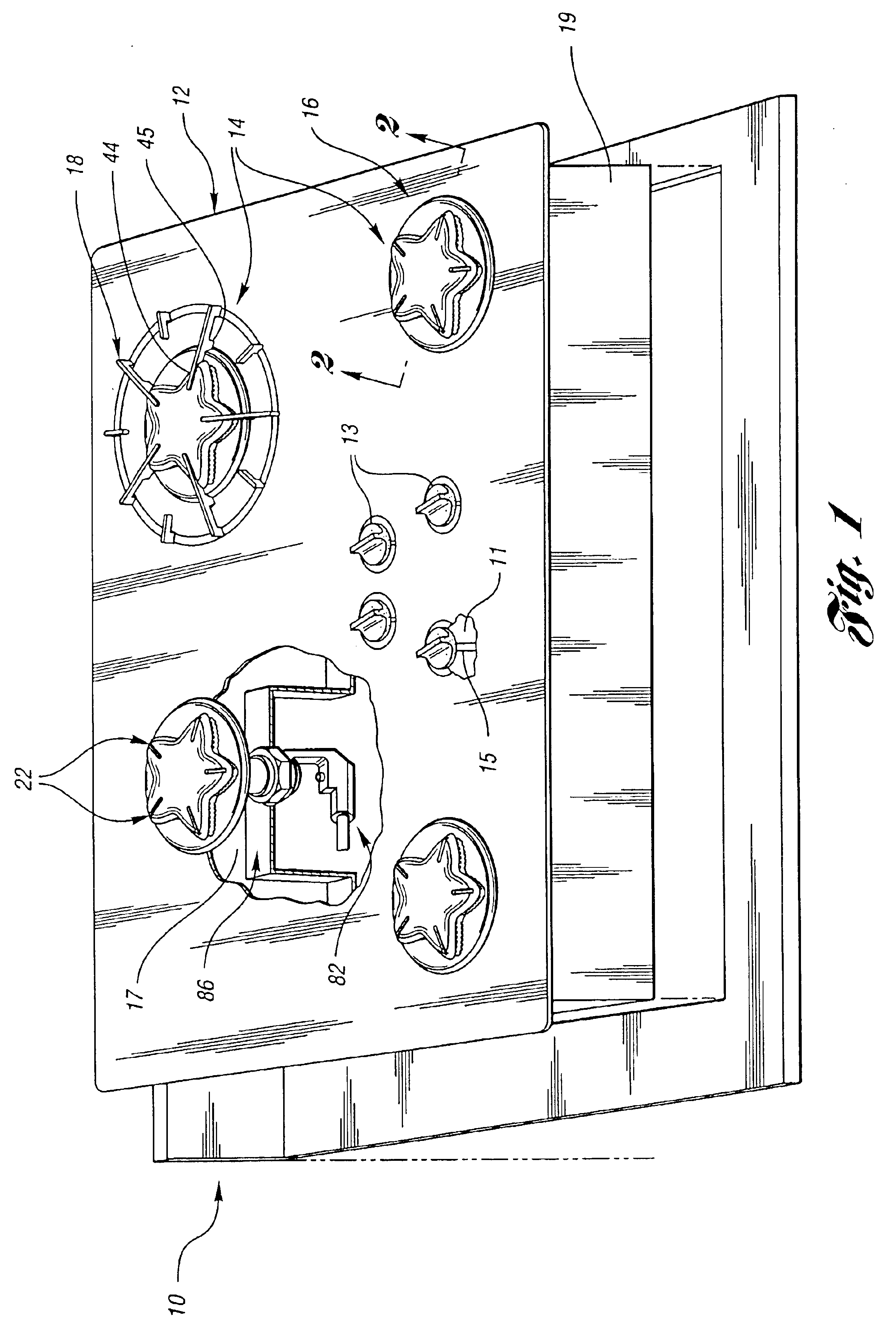
Referring first to FIG. 1, a cooking appliance 10 is shown having a cooktop 12 including a plurality of burners 14. The cooktop 12 includes surface panel 16 having a plurality of openings 17 defining the positions for each of the burners 14. Each burner supports a grate 18 to support a cooking utensil, such as a pot, pan or kettle over the burner. In the preferred embodiment, the surface panel 16 forms a sealed burner arrangement which is to be discussed in greater detail below. Nevertheless, the present invention is not limited to that context, and may also be employed with “open” burner arrangements that do not seal to a cooktop surface. In addition, control knobs 13 are carried on valve stems 15 protruding through openings 11 in the cooktop 12. The control knobs 13 are used to control the burner operation including the valve for controlling the flow of gas to the burner, and preferably, to also control the ignition of the burner in a well known manner, for example, as disclosed ...


PUM


Abstract

A cooking appliance includes burners having ports that are aligned in a defined alignment with respect to an adjacent structure of a burner body or the cooking appliance within a piloting zone so that the adjacent structure guides the formation of a flame kernel at an outlet of the port. The adjacent structure may be ports which also form flame kernels withing the piloting zone of the burner port outlet, a structural portion of the burner body such as an extended lip protruding beyond the burner port or a separate structure such as a flame rod or other target that stabilizes the flame kernels at the burner port outlet. Such structures provide a method for improving the turndown ratio of burners by preventing lifting or backlash of the flame kernels generated at the burner port outlets by aligning the ports in conjunction with an adjacent structure within a piloting zone.

Description

BACKGROUND OF THE INVENTION1. Field of the InventionThe present invention relates generally to cooking appliances having gas burners with ports aligned to a predetermined relationship with adjacent structures to contribute to piloting of flame kernel patterns.2. Background ArtMany previously known cooktops using gas burners include circular burners in order to provide a ring of ports that distribute heat at a consistent radial dimension from the burner. Such burners form a circular ring of flame kernels adjacent the outlet of the ports in the burner. Typically, the radial alignment of the ports limits interaction of the flame kernels generated at the ports, and as a result, limits the turndown ratio, the ratio of a burner's energy output per unit time (power, expressed in BTU per / hour) at maximum gas flow rate divided by the power at the minimum sustainable gas flow rate. The resulting flame kernel is then limited by the size of the port, and the limited range of gas flow rates, and...

Claims


Application Information

Patent Timeline
Patent Type & Authority Patents(United States)
IPC IPC(8): F23D14/04F23D14/06F23D14/10F23D14/26F24C3/08F23D14/00
CPCF23D14/045F23D14/06F23D14/105F24C3/085F23D14/26F23D2203/102F23D2900/14042F23D2900/14064
Inventor JENNINGS, RALPH ERNEST
Owner BSH HOME APPLIANCES CORP
Why Eureka
Try Eureka