Gas Heating Appliance

a technology for gas heating appliances and cooktops, applied in the direction of combustion process, combustion ignition, domestic heating details, etc., can solve the problems inability to clean, and inability to adjust the temperature of the cooking vessel, etc., and achieve the effect of high turn-down ratio

Active Publication Date: 2008-11-27
FISHER & PAYKEL APPLIANCES LTD
View PDF30 Cites 9 Cited by
  • Summary
  • Abstract
  • Description
  • Claims
  • Application Information

AI Technical Summary

Benefits of technology

[0007]Accordingly, it is an object of the invention to provide a gas burner with a high turn-down ratio, and / or at least provide the public with a useful choice.

Problems solved by technology

Trivets and burner components comprise many complex shapes and surfaces which can make cleaning more difficult.
These structures are also visually complex.
However in some cases it may be possible for a user to re-assemble these components incorrectly, which can lead to instability of the cooking vessel and / or incorrect operation of the burner.
Incorrect assembly or operation of the gas cooktop components may be hazardous.
The efficiency of conventional gas burners is limited by the need to maintain sufficient clearance around the burner head to allow the flame to draw in enough of the surrounding air to achieve complete combustion of the fuel gas.
The operating range of conventional cooktop gas burners is limited to the performance range of the venturi and the burner ports.
The fixed geometry of the venturi and fuel gas jet limit the range over which this type of burner will operate.

Method used


Image

  • Gas Heating Appliance
  • Gas Heating Appliance
  • Gas Heating Appliance

Examples


Embodiment Construction

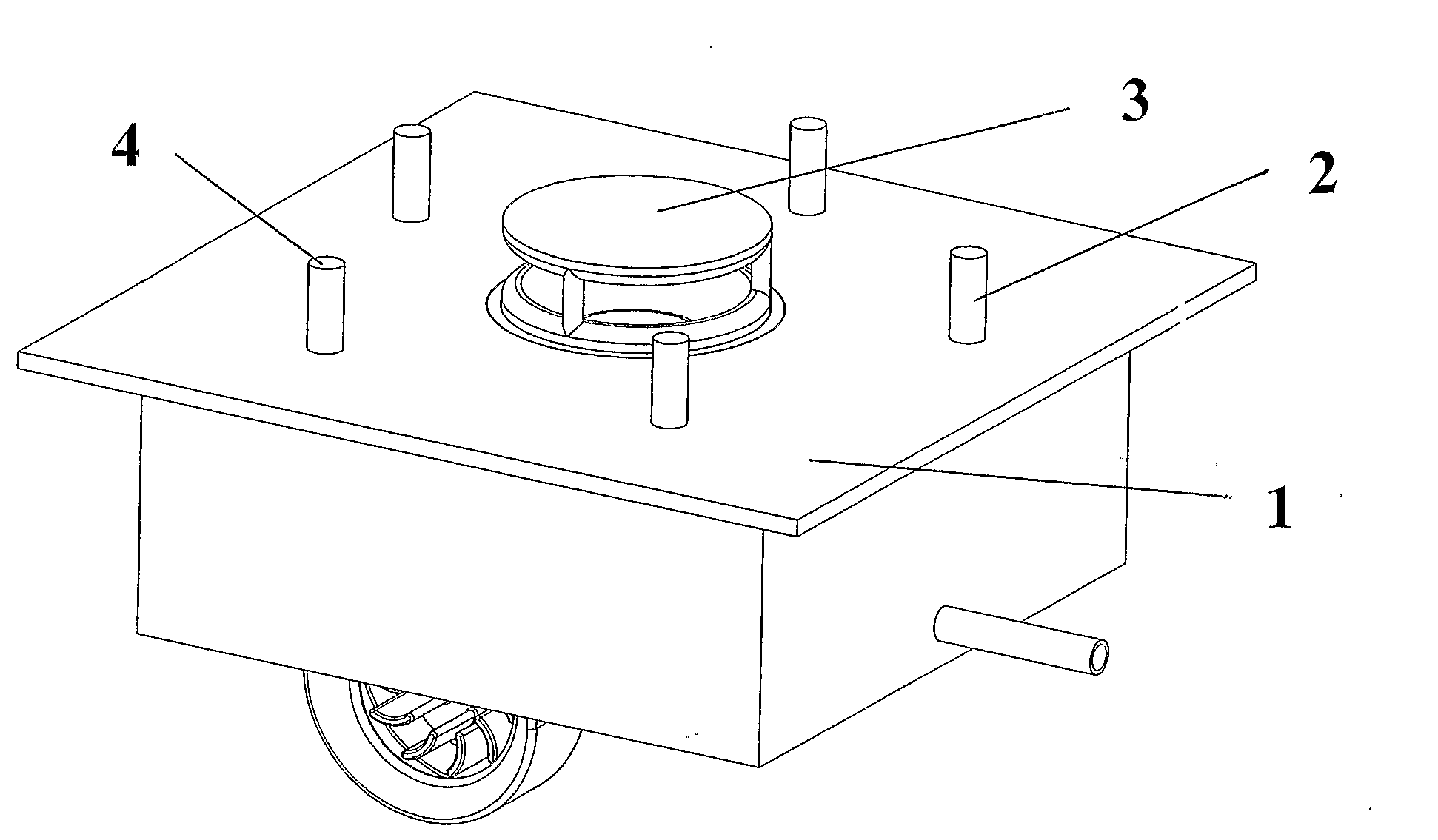
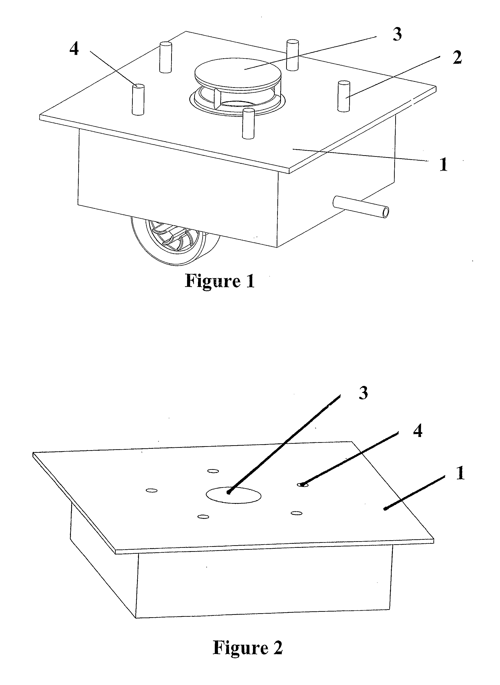
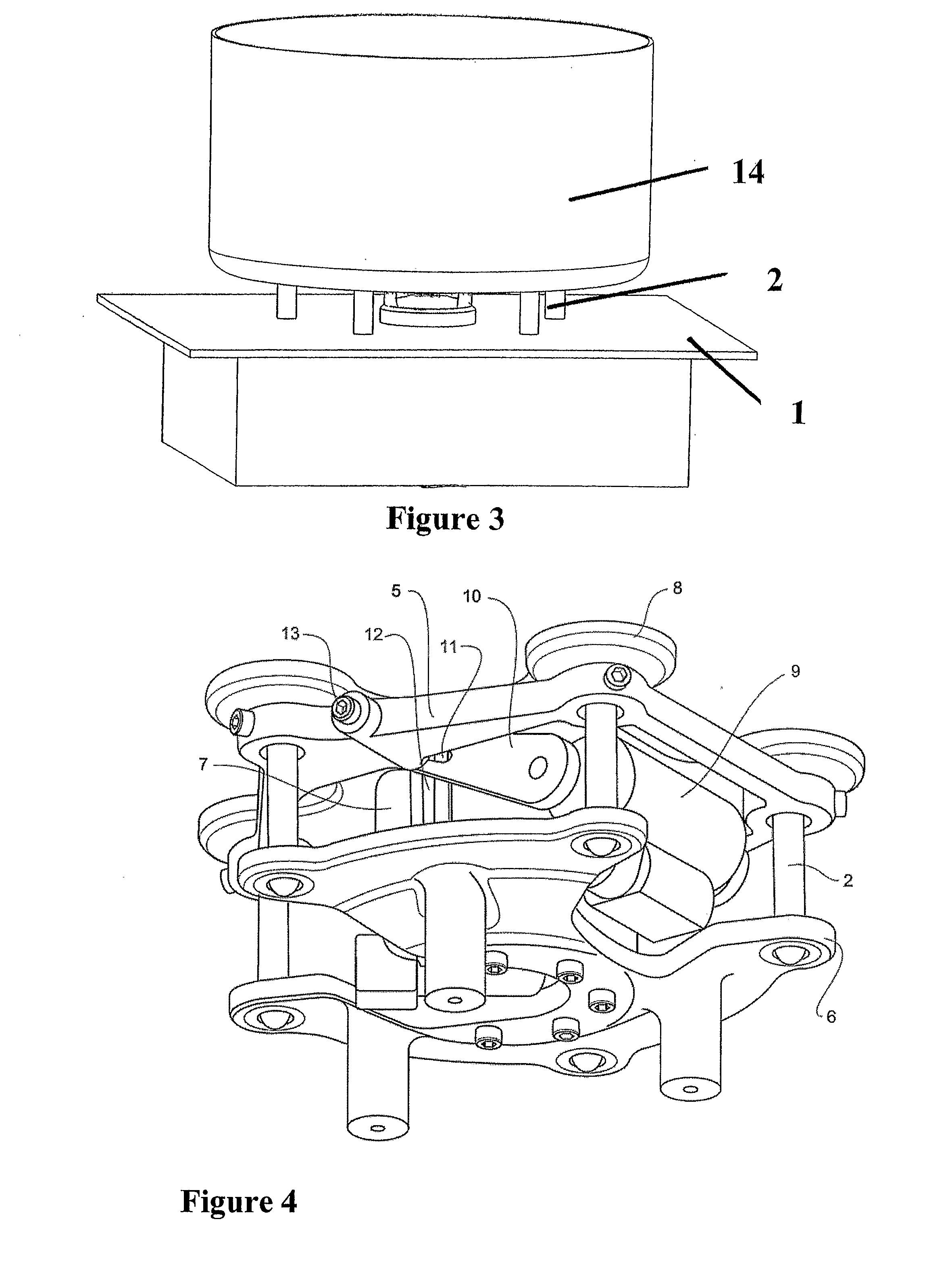
[0094]Throughout the description reference is made to the accompanying Figures which are labelled with numerals in order to more clearly describe the invention. A number of different embodiments are described and illustrated, representing various combinations of features Where possible like reference numerals have been used across different embodiments to illustrate similar or shared components.

[0095]In one aspect the present invention provides an easily cleaned gas cooktop surface. The surface is not cluttered by a traditional trivet and can thereby be used for other purposes when not in use for cooking. The cooktop surface is preferably substantially planar but may include raised regions (especially around apertures in the cooktop surface) to contain spillage of food or liquids on the spill plane of the cooktop in order to reduce the potential for spillages to leak into the appliance. It will be readily appreciated that cooktop surfaces usually include multiple burners, which may ...


PUM


Abstract

In one aspect the invention discloses an improved gas burner with a high turn-down ratio. The improved burner includes first and second gas flow passages (44, 47), a flame front locator (49) in one of the passages of the burner head. Fuel gas is injected into an end of one of one of the passages (47) and is ignited to establish a flame at the flame front locator (49). Secondary combustion air is provided through the other of the passages (44) which on a high setting enables secondary combustion and on a low setting may mix with the hot gases and cool them resulting in a lower temperature at the cooking vessel.

Description

FIELD OF THE INVENTION[0001]The invention relates to improvements to gas heating appliances and in particular gas cooktops.BACKGROUND[0002]There are a number of methods known in the art of providing heat in a cooktop. One preferred method is to use a gas burner which is able to deliver high levels of heating and which responds fairly quickly to desired changes in level. An example of a typical gas burner is described in WO 01 / 50065. It is typical that the finest level of control will be desired at the lower levels of output range for various cooking duties. In order to achieve good level control, various fuel gas flow control valves have been proposed such as those described in U.S. Pat. No. 5,009,393 and WO 01 / 33118.[0003]In a typical gas cooktop a trivet is provided to support a cooking vessel above the gas burner and attempts have been made previously to accommodate various shapes of cooking vessels. Examples of trivet arrangements are described in U.S. Pat. No. 6,588,417, WO 02 / ...

Claims


Application Information

Patent Timeline
Patent Type & Authority Applications(United States)
IPC IPC(8): F24C3/08F16K21/00F23Q25/00
CPCF23D14/105F23D14/36F23L1/00F23L1/02Y10T74/18312F23L9/02F24C3/085F24C15/107F23L5/02Y10T137/87249Y10T137/85978F23M9/02F23D14/02
Inventor GRAHAM, LINDSAY GEORGEBROWN, SIMON DENZIL
Owner FISHER & PAYKEL APPLIANCES LTD
Why Eureka
Try Eureka