Combustion apparatus and method for radiating wall heating system

a combustion apparatus and radiating wall technology, applied in lighting and heating apparatus, combustion using lump and pulverulent fuel, combustion types, etc., can solve the problems of reducing the overall efficiency and heating capacity of the radiating wall system, reducing the efficiency, effectiveness and stability of the burner, and reducing the performance. , to achieve the effect of reducing the production of harmful nox emissions, and reducing the drift and impingement of flames

Active Publication Date: 2005-12-27
ZEECO
View PDF10 Cites 9 Cited by
  • Summary
  • Abstract
  • Description
  • Claims
  • Application Information

AI Technical Summary

Benefits of technology

[0011]The present invention provides an improved radiant wall burner and an improved method of producing combustion energy in radiant wall systems. The inventive burner and method satisfy the needs and alleviate the problems discussed above. The inventive burner and method are ...

Problems solved by technology

This reduces the efficiency, effectiveness, and stability of the burner 14 and also reduces the overall efficiency and heating capacity of the radiant wall system 2.
The impingement or near impingement of the burner flame 30 on the p...

Method used


Image

  • Combustion apparatus and method for radiating wall heating system
  • Combustion apparatus and method for radiating wall heating system
  • Combustion apparatus and method for radiating wall heating system

Examples


embodiment 100

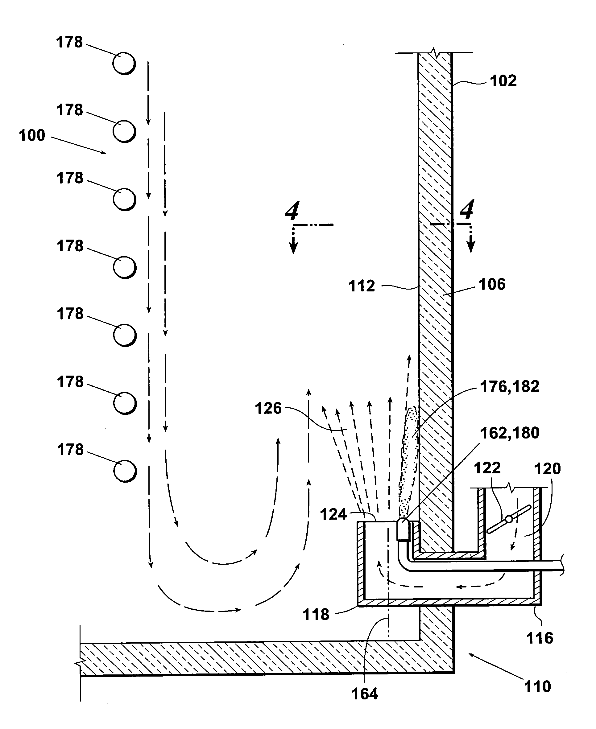
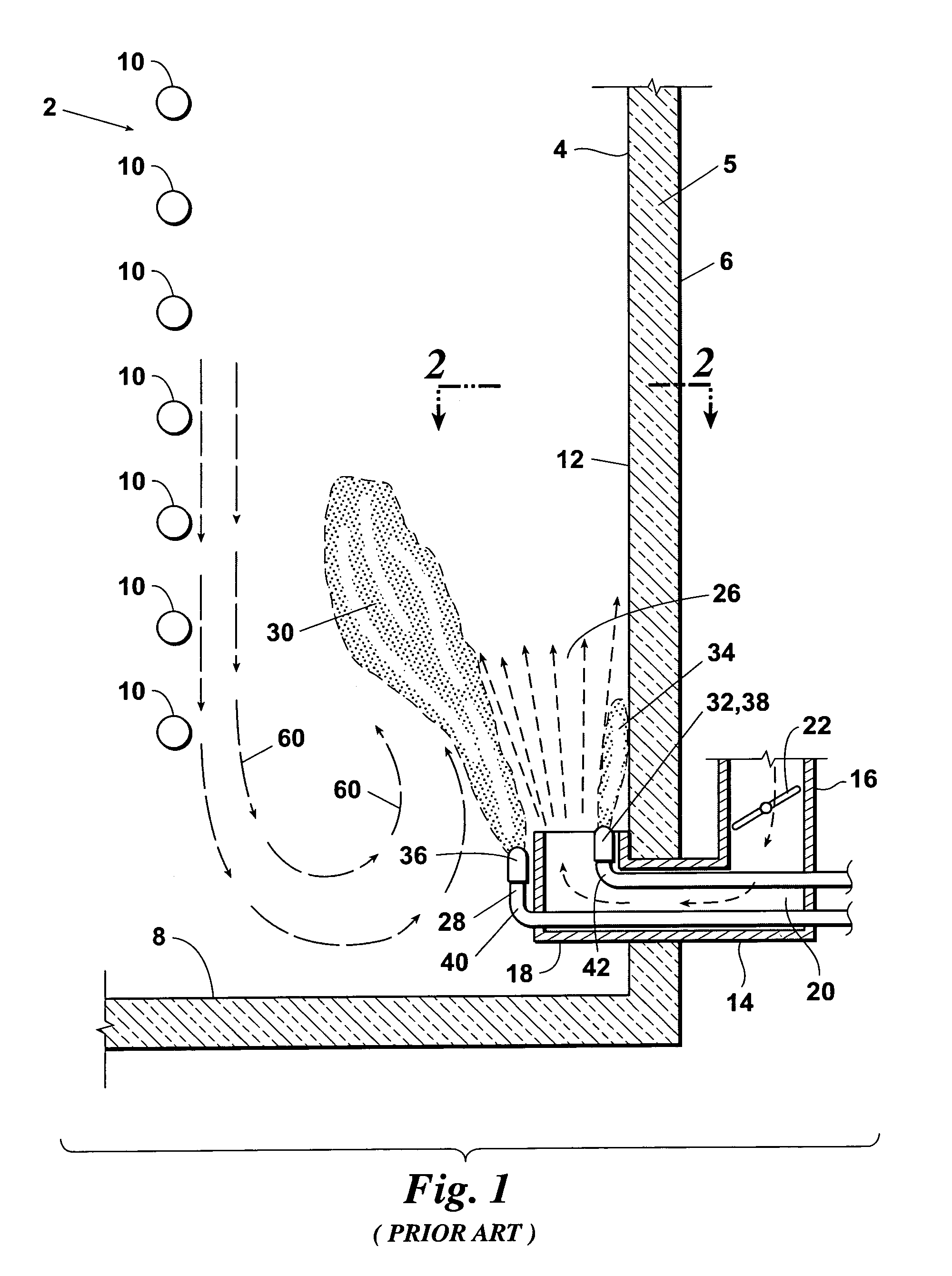
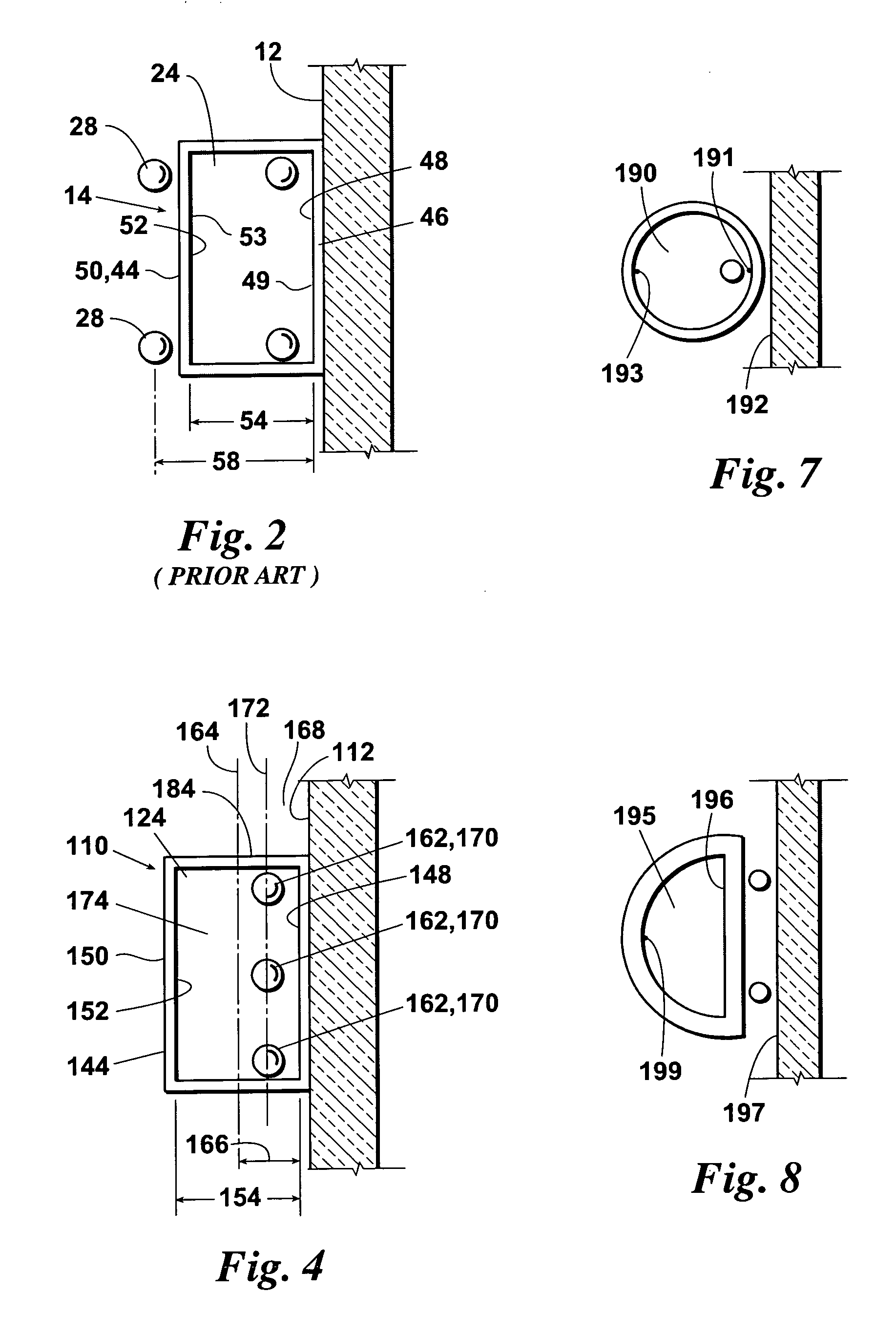
[0024]An embodiment 100 of the inventive heating system is depicted in FIGS. 3 and 4. The inventive heating system 100 includes at least one inventive improved burner 110. As with the prior art burner 14, the inventive burner 110 includes: a housing 116; a burner wall 118 which extends horizontally from housing 116 through the outer wall 106 and through the radiating internal wall 112 of the heater 102; an air flow passage 120 extending through burner housing 116 and burner wall 118; an air flow damper or other regulator 122 within the burner housing 116; and an upper opening 124 for discharging the combustion air 126 upwardly into heater 102.

[0025]In the inventive burner, the upper combustion air opening 124 and peripheral wall 144 surrounding the upper opening 124 can be circular, oval, rectangular (including square), or any other desired shape. As with prior art burner 14, the combustion air opening 124 of inventive burner 110 is rectangular. Consequently, the near boundary 148 o...

embodiment 200

[0032]An alternative embodiment 200 of the inventive burner is illustrated in FIGS. 5 and 6. The inventive burner 200 is substantially the same as inventive burner 110 except that: (a) the burner 200 extends vertically through the floor 202 of the furnace rather than through the side wall 204; (b) two of the fuel ejectors 206 of inventive burner 200 are positioned in the near wall 208 such that they are not located within the air discharge opening 210; and (c) the near wall 208 of the inventive burner 200 includes an upwardly inclined guide wall 212 which assists in guiding the burner flame upwardly against the radiant wall 214.


PUM


Abstract

A burner and combustion method for a radiant wall heating system wherein each burner fuel ejector is positioned such that at least a substantial portion of the burner combustion air is discharged from an area beyond the ejector located the greatest distance from the radiant wall.

Description

FIELD OF THE INVENTION[0001]The present invention relates to burners and combustion methods for use in heating systems having upwardly extending radiating walls for radiating combustion energy.BACKGROUND OF THE INVENTION[0002]Radiant wall heating systems are commonly employed in chemical, petroleum, and other industrial processes. A typical prior art radiant wall heating system 2 is illustrated in FIGS. 1 and 2. The prior art radiant wall system 2 comprises: a furnace, boiler, or other fired heater 4 having a housing 5, an outer wall 6, and a floor 8; a plurality of process tubes 10 which carry the process fluid through the housing 5; an upwardly extending radiating wall 12 within housing 5; and at least one radiant wall burner 14. The radiant wall 12 within heater 5 is typically comprised of a radiating ceramic tile material or other material which will radiate the combustion energy generated by burner 14 toward and onto the process tubes 10.[0003]The prior art burner 14 shown in F...

Claims


Application Information

Patent Timeline
IPC IPC(8): F23D14/22
CPCF23D14/22F23D2900/00011
Inventor ZINK, DARTONISAACS, REXMCDONALD, JOHNKIRK, TIMLITTLE, CODY
Owner ZEECO
Why Eureka
Try Eureka