On board refueling vapor recovery system and fuel vapor passage using for the same

a technology of refueling vapor recovery and fuel vapor passage, which is applied in the direction of combustion air/fuel air treatment, liquid handling, packaging goods type, etc., to achieve the effect of reducing the amount of released fuel evaporative emissions

Inactive Publication Date: 2005-02-08
HONDA MOTOR CO LTD
View PDF12 Cites 32 Cited by
  • Summary
  • Abstract
  • Description
  • Claims
  • Application Information

AI Technical Summary

Benefits of technology

It is an object of the invention to provide an on board refueling vapor recovery system and a fuel vapor passage which requires only a less number of man hours for assembling and a limited space for installation and which can reduce an amount of released fuel evaporative emissions.
According to the construction of the second aspect of the invention, the check valve is integrated (constructed to be integrated) with the container of the float valve in the fuel tank. Owing to this, the reduction in the number of man hours for assembling the second fuel vapor passage can be attained.

Problems solved by technology

Fuel evaporative emissions released from a fuel tank of a vehicle is one of the major sources of air pollution when the fuel tank is refilled with a fuel.

Method used


Image

  • On board refueling vapor recovery system and fuel vapor passage using for the same
  • On board refueling vapor recovery system and fuel vapor passage using for the same
  • On board refueling vapor recovery system and fuel vapor passage using for the same

Examples


first embodiment

Firstly, an on board refueling vapor recovery system according to a first embodiment will be described.

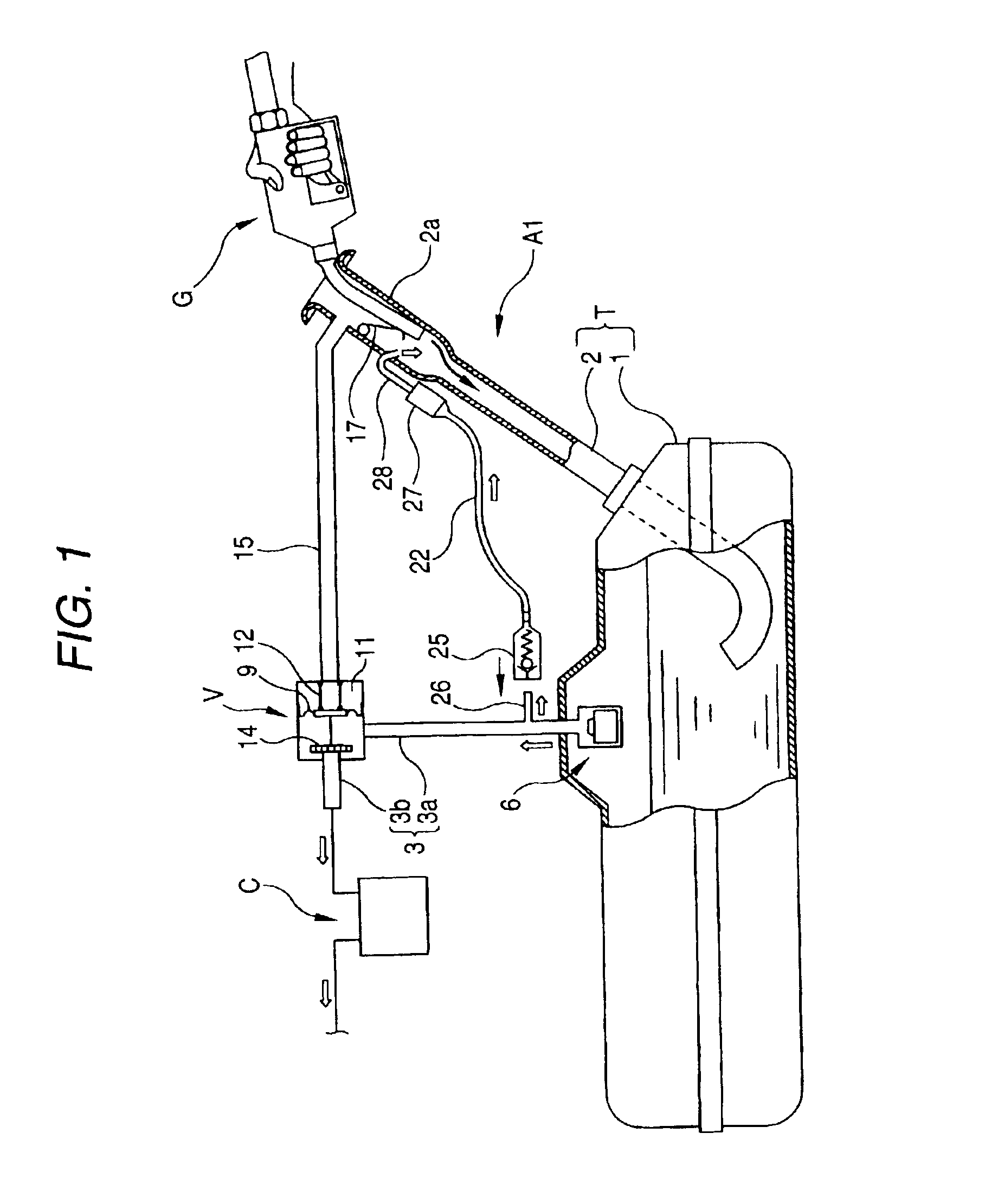
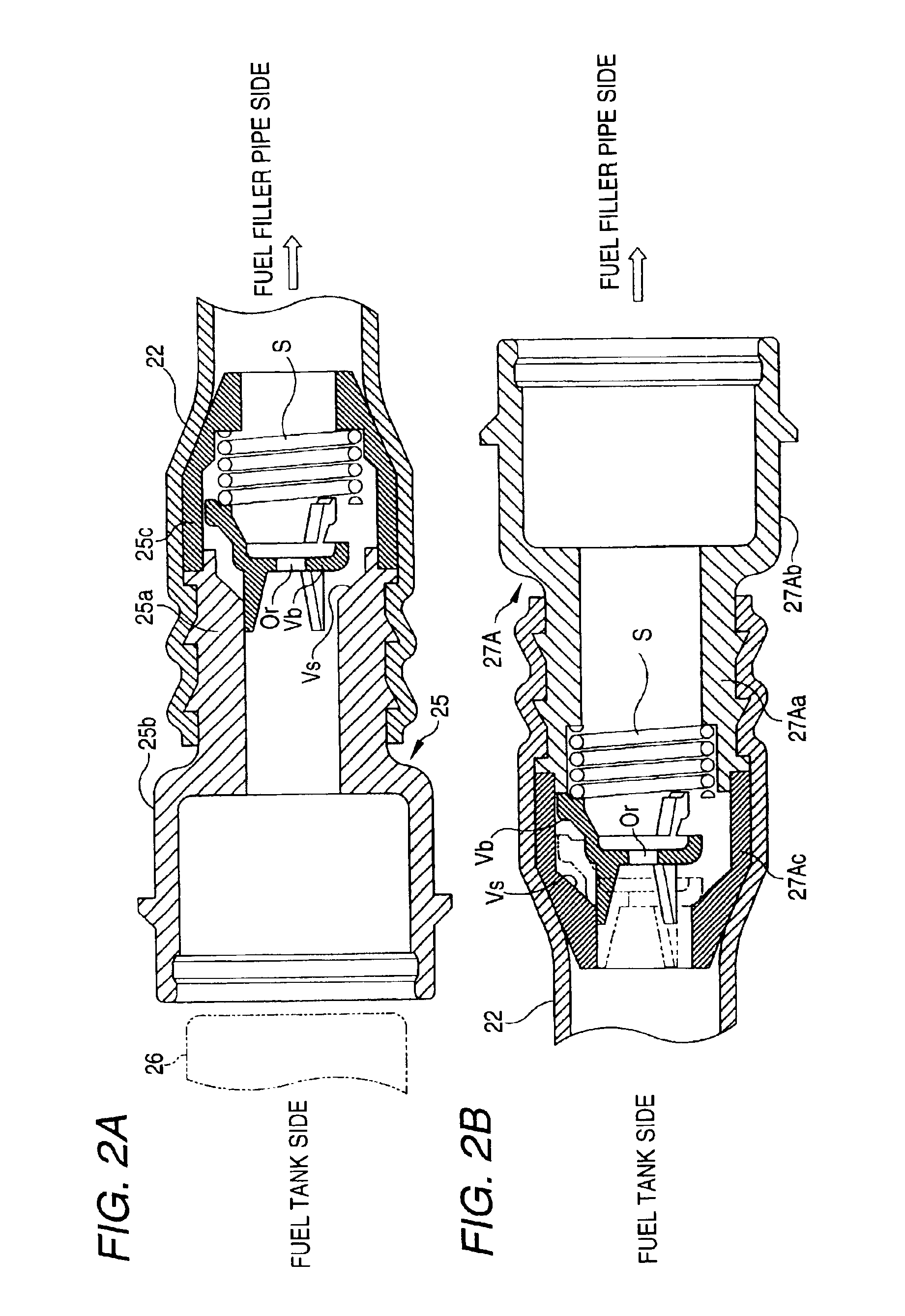
FIG. 1 is a cut-away sectional view showing the overall construction of the on board refueling vapor recovery system according to the first embodiment. FIG. 2A is a sectional view of a first quick connector into which a check valve is integrated. FIG. 2B is a sectional view showing a modified example of a second quick connector. FIG. 3A is a sectional view of a modified example of the first quick connector, and FIG. 3B is another modified example of the second quick connector.

As shown in FIG. 1, a fuel tank T includes a tank main body 1 and a fuel filler pipe 2 provided to extend from the tank main body 1 upwardly in an inclined fashion, and a fuel filler inlet portion 2a having a larger diameter. The fuel filler inlet portion 2a is provided at an upper end of the fuel filler pipe 2.

In addition, one end portion of a first fuel vapor passage 3 connects to an upper portion of the tan...

second embodiment

Next, an on board refueling vapor recovery system according to a second embodiment will be described. Note that like reference numerals to those used in the first embodiment will be imparted to like members and elements to those described in the first embodiment, and the description thereof will be omitted.

FIG. 4 is a cut-away sectional view showing the overall construction of the on board refueling vapor recovery system according to the second embodiment of the invention. FIG. 5 is a partially cut-away view showing a float valve container in a fuel tank into which a check valve is integrated.

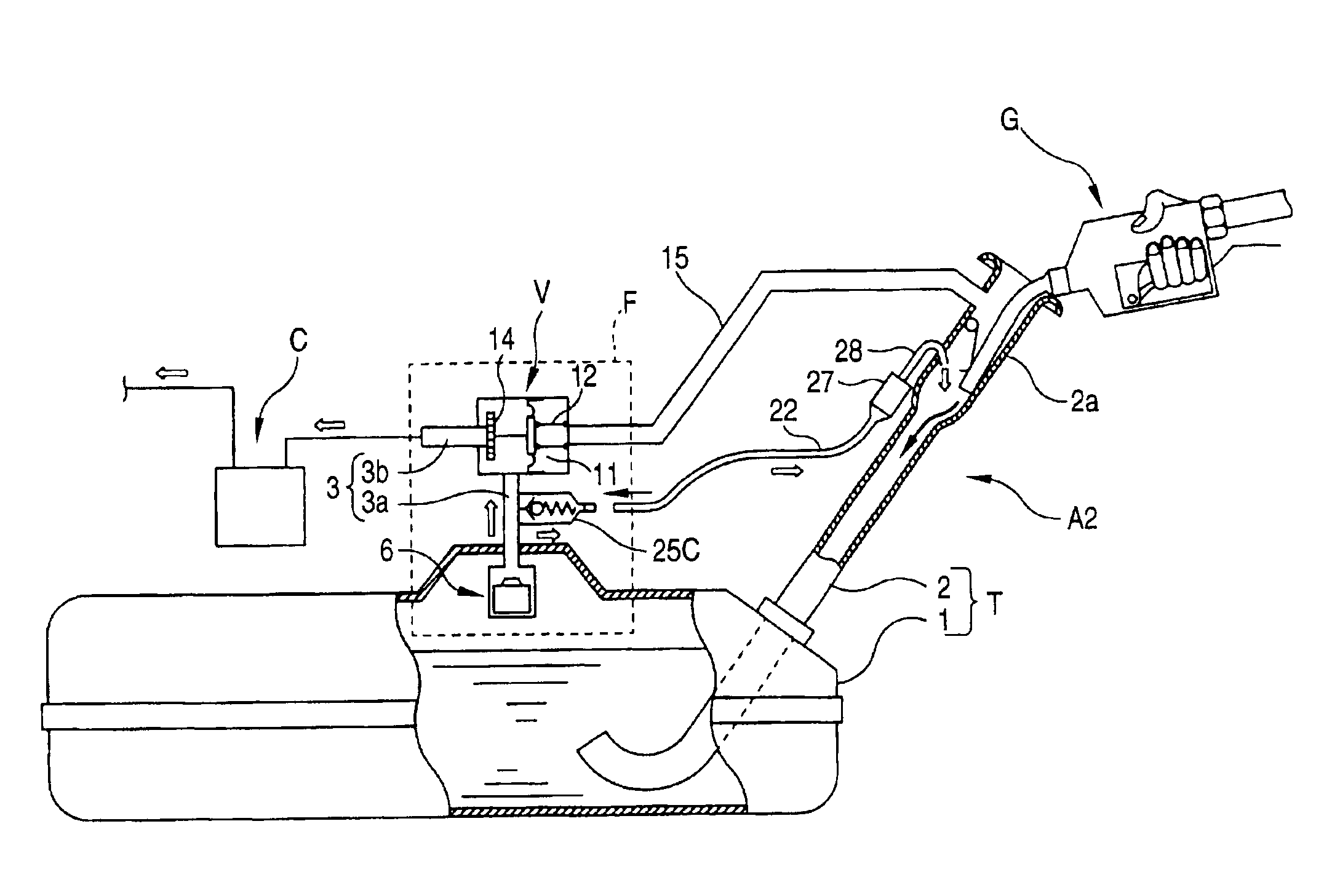
As shown in FIG. 5, a float valve 6, a valve V, a check valve 25C and a first fuel passage 3 (3a, 3b) which are surrounded by broken lines in FIG. 4 are integrally accommodated formed in a float valve container F.

The check valve 25C is provided in a sleeve protruding from a right-hand side of an upper portion of the float valve 6. A connecting portion of the check valve 25 to a second fuel vapo...

third embodiment

Next, an on board refueling vapor recovery system according to a third embodiment will be described. Note that like reference numerals to those used in the first and second embodiments will be imparted to like members and elements to those described in the first and second embodiments, and the description thereof will be omitted here.

FIG. 6 is a cut-away view showing the overall construction of an on board refueling vapor recovery system according to a third embodiment.

As shown in FIG. 6, no second fuel vapor passage 22 is connected to a first fuel vapor passage 3 (3a) of the on board refueling vapor recovery system according to the third embodiment of the invention as with the first and second embodiments.

Owing to this, there is provided neither a connecting pipe 26 (refer to FIG. 1) like the one provided in the first embodiment nor a check valve 25C (refer to FIG. 4) like the one provided in the second embodiment. Instead, a vapor return joint member 51 is provided directly on a t...


PUM

PropertyMeasurementUnit
timeaaaaaaaaaa
diameteraaaaaaaaaa
pressureaaaaaaaaaa

Abstract

An on board refueling vapor recovery system includes a first fuel vapor passage for connecting a fuel tank with a canister, a second fuel vapor passage for connecting an inlet portion of a fuel filler pipe with the fuel vapor passage (a tank main body) and a check valve in the second fuel vapor passage. The check valve is integrated with a first quick connector of a resin hose (a resin tube) which constitutes the second fuel vapor passage. Therefore, the number of man hours required for assembling the on board refueling vapor recovery system can be reduced. In addition, the space required for installing any of the on board refueling vapor recovery system can also be reduced. Furthermore, the amount of released fuel evaporative emissions or fuel evaporative emissions can be reduced.

Description

BACKGROUND OF THE INVENTION1. Field of the InventionThe present invention relates to an on board refueling vapor recovery system for controlling an amount of fuel evaporative emissions released when a fuel tank of a vehicle is refilled with fuel and fuel vapor passage using for the same.2. Description of the Related ArtFuel evaporative emissions released from a fuel tank of a vehicle is one of the major sources of air pollution when the fuel tank is refilled with a fuel. Due to this, for example, in the United States of America, an amount of fuel evaporative emissions released at the time of refilling fuel tanks of vehicles is regulated.To cope with an regulation of the amount of the fuel evaporative emissions, on-board evaporative recovery (called ORVR) system are equipped on vehicles so that the amount of fuel evaporative emissions is controlled. an known on board refueling vapor recovery of this type is described in the specification of Japanese Patent No. 3158170 by the applican...

Claims


Application Information

Patent Timeline
Patent Type & Authority Patents(United States)
IPC IPC(8): B60K15/035B60K15/03F02M25/08F02M37/00
CPCB60K15/03519B60K2015/03453Y10T137/86324
Inventor NAKAJIMA, TAKEAKINAKAMURA, TADAHISAHONDA, TAKESHISHIDA, KIYOFUMIINOUE, HIROTO
Owner HONDA MOTOR CO LTD
Why Eureka
Try Eureka