Heat exchanger

a technology of heat exchanger and heat exchanger plate, which is applied in the direction of indirect heat exchanger, manufacturing tools, lighting and heating apparatus, etc., to achieve the effect of improving connection

Inactive Publication Date: 2005-02-08
BEHR GMBH & CO KG
View PDF13 Cites 15 Cited by
  • Summary
  • Abstract
  • Description
  • Claims
  • Application Information

AI Technical Summary

Benefits of technology

One object of the present invention is to provide an improved heat exchanger, particularly one having an improved connection of collecting tube and collector in a condenser of the type set out in the introduction, such that a const

Problems solved by technology

For a brazed condenser, such an operation is not typical, i.e. it is disadvant

Method used


Image

  • Heat exchanger
  • Heat exchanger
  • Heat exchanger

Examples


Embodiment Construction

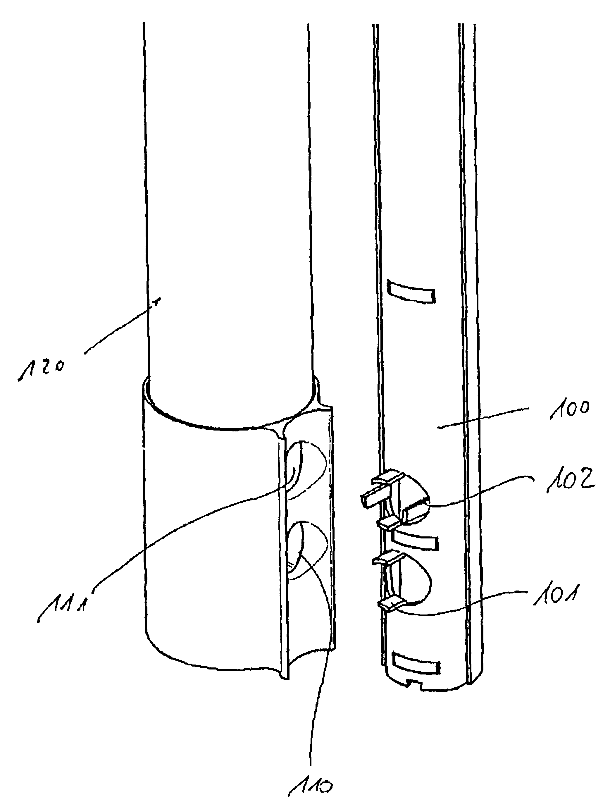
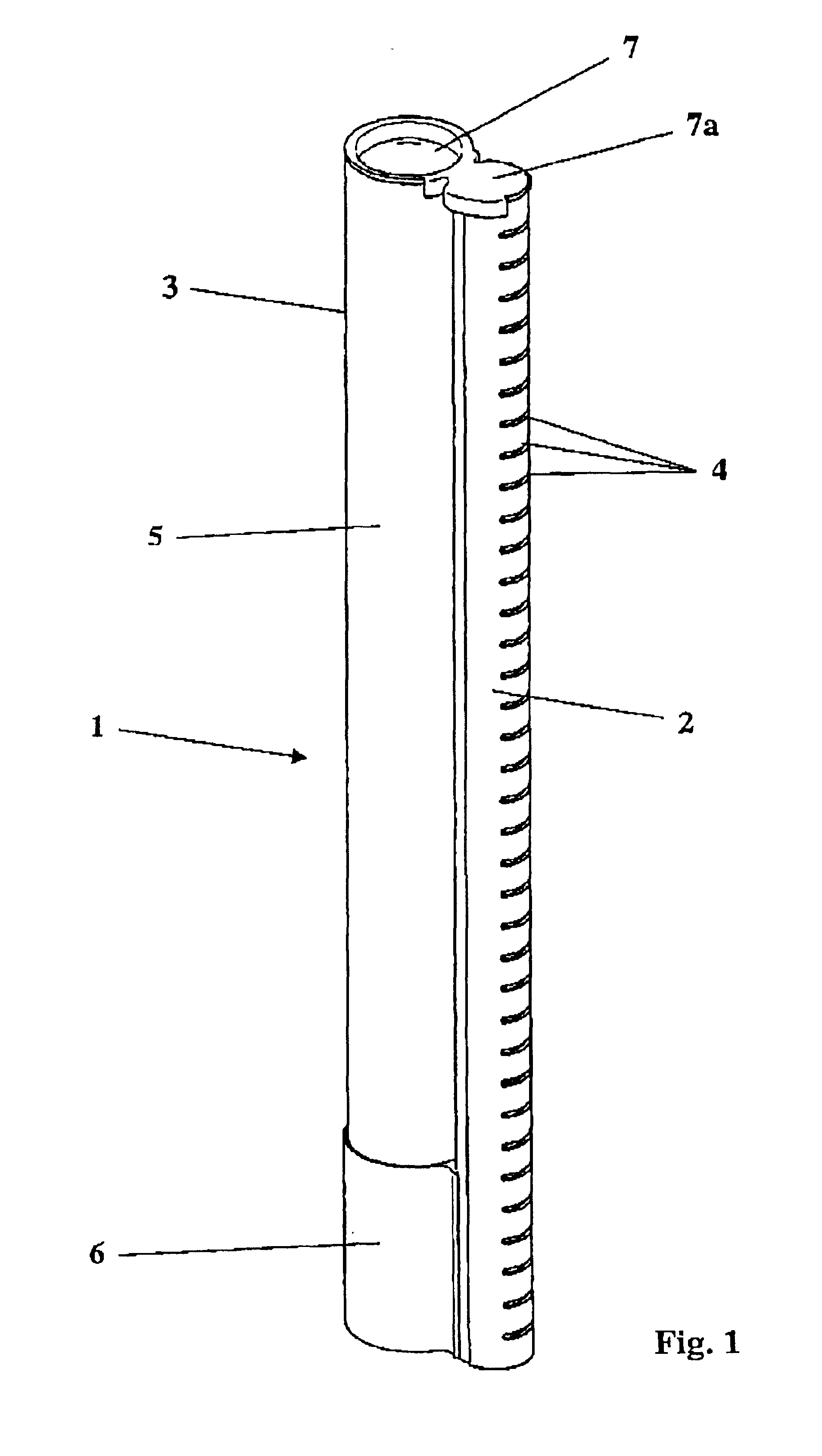
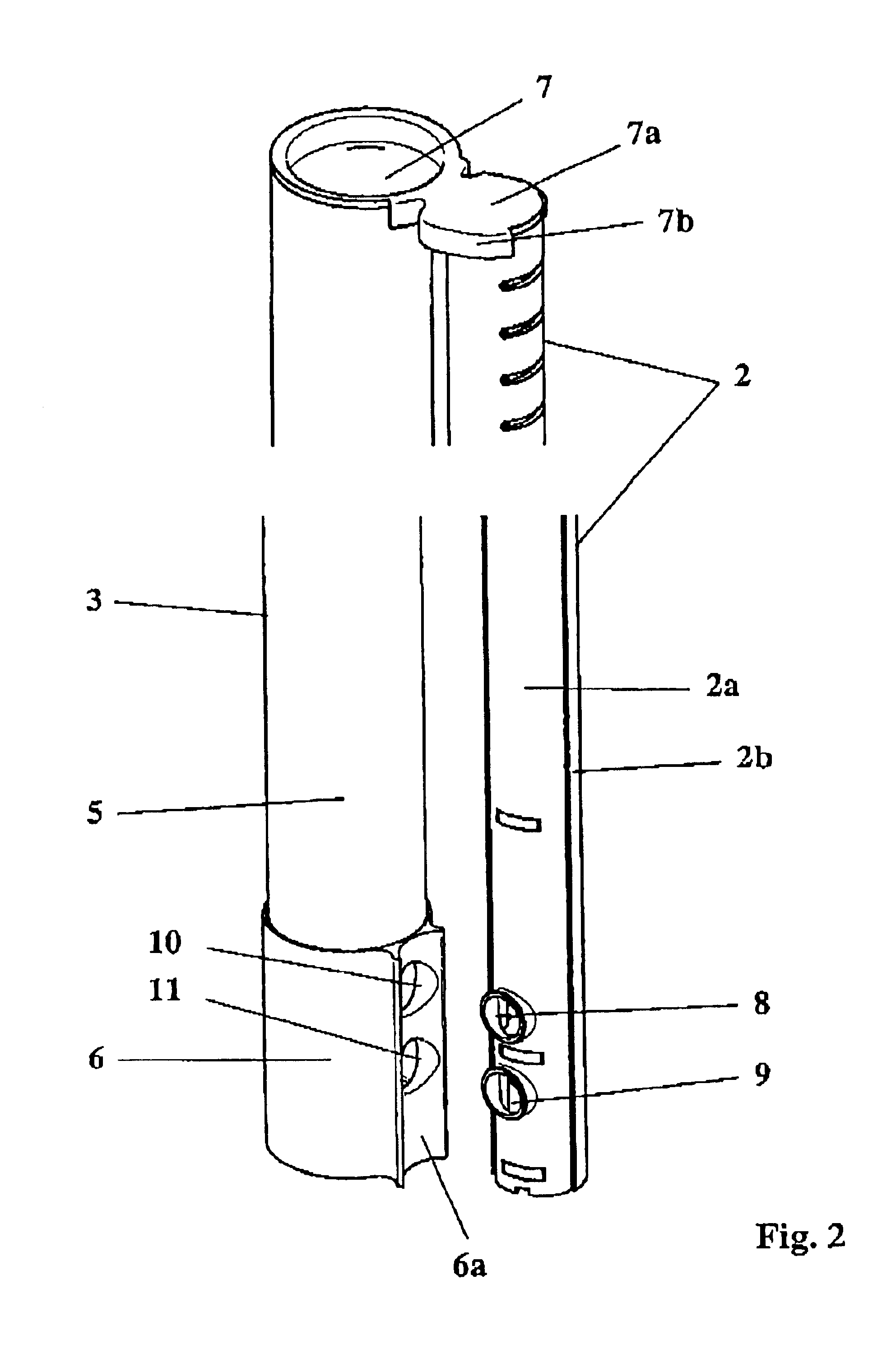
According to the invention, the collecting tube and collector are fixed relative to one another via a cover and are positioned in such a way that they can then be brazed without further fixing aids. The cover is, on the one hand, pressed into the tube end of the collector and, on the other hand, engages with a lateral extension, such as a cap, around the adjacent collecting tube. Both the closure part pressed into the tube end and also the cap-shaped extension are brazed to the two tube ends so that a secure connection between collector and collecting tube is then produced. By means of this cover, therefore, a construction is made available which is expedient for brazing, so that it is possible to dispense with further fixing means, such as tack-welding.

According to one advantageous embodiment of the invention, the collecting tube is designed in two parts, i.e., it has, on the one hand, a base part with apertures for the flat tubes and, on the other hand, a cover part which is braze...


PUM

PropertyMeasurementUnit
Forceaaaaaaaaaa

Abstract

The invention relates to a heat exchanger, in particular a refrigerant condenser, especially for a motor vehicle air-conditioning unit. The heat exchanger is comprised of a block of tubes and fins and of collecting tubes which are arranged on both sides and receive the ends of the tubes, and of a collector which is arranged parallel to a collecting tube. A method for manufacturing the heat exchanger is also disclosed.

Description

CROSS-REFERENCE TO RELATED PATENT APPLICATIONSThe right of priority under 35 U.S.C. §119(a) is claimed based on Federal Republic of Germany Priority Application 101 54 891.5, filed Nov. 8, 2001, and Federal Republic of Germany Priority Application 102 29 831.9, filed Jul. 3, 2002, the disclosures of which, including the specification, drawings, claims and abstract of each, are incorporated herein by reference.BACKGROUND OF THE INVENTIONThe present invention relates to a heat exchanger, in particular, a refrigerant condenser, and more particularly to such a heat exchanger for motor vehicle air-conditioning units. The heat exchanger includes a block of tubes and fins and collecting tubes which are arranged on both sides and receive the ends of the tubes of the block of tubes. It also includes a collector which is arranged parallel to one of the collecting tubes and is in refrigerant communication with the collecting tube via two overflow openings.Such collectors can be formed from a f...

Claims


Application Information

Patent Timeline
IPC IPC(8): F28F9/02F25B39/04
CPCF25B39/04F28F9/0214F25B2339/044F28F2220/00F25B2339/0446F25B2339/0442
Inventor KASPAR, MARTINKOHL, MICHAELWOELK, GERRIT
Owner BEHR GMBH & CO KG
Why Eureka
Try Eureka