Self-standing type bag-shaped container having evaluating and flow velocity controlling functions

a self-standing, bag-shaped container technology, applied in the direction of pliable tubular containers, transportation and packaging, liquid transferring devices, etc., can solve the problems of reducing the capacity of containers, affecting the storage effect, so as to achieve convenient storage

Inactive Publication Date: 2005-02-08
HAGIHARA TADASHI
View PDF15 Cites 16 Cited by
  • Summary
  • Abstract
  • Description
  • Claims
  • Application Information

AI Technical Summary

Benefits of technology

Furthermore, the container further comprises a flow velocity control mechanism including a wall disposed in a flow velocity control unit and intersecting the inflow direction from a vent hole at a right angle so that the content flow may be impinged, when the content comes from the inside of the container body into the flow velocity control unit, upon the wall, to eliminate the flow velocity in the inflow direction.
The self-standing container such as the stand pouch of the invention has the construction thus far described so that it can be optimized for storing not only wine, sake or whiskey, which are effected by contact with air because they will be oxidized with the air, but also fruit beverages, vegetable juices or other beverages. The invention can provide a vacuum type container which will not lose its self-standing property e

Problems solved by technology

However, these glass bottles are heavy and brittle so that they are seriously troublesome to handle.
Therefore, the hard containers are not suited for storing the beverages effected by contact with the air, such as wine, sake, whiskey, fruit beverages, and vegetable juices.
It is easily understood how wasteful this is, if a case in which a container that is filled with a beverage is stored in a refrigerator is imagined.
It has also been found that the container has its capacity reduced and loses its self-st

Method used


Image

  • Self-standing type bag-shaped container having evaluating and flow velocity controlling functions
  • Self-standing type bag-shaped container having evaluating and flow velocity controlling functions
  • Self-standing type bag-shaped container having evaluating and flow velocity controlling functions

Examples


first embodiment

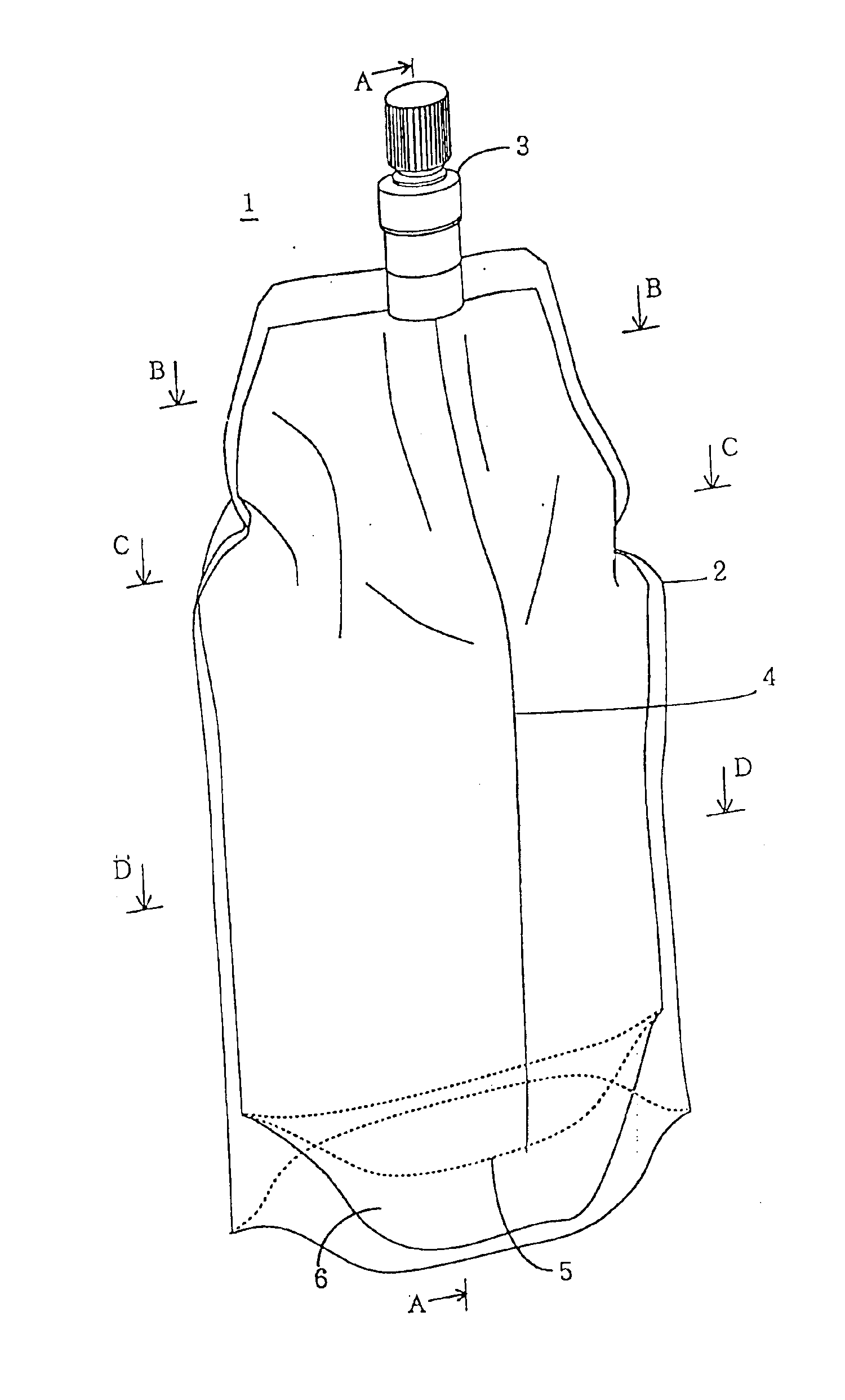
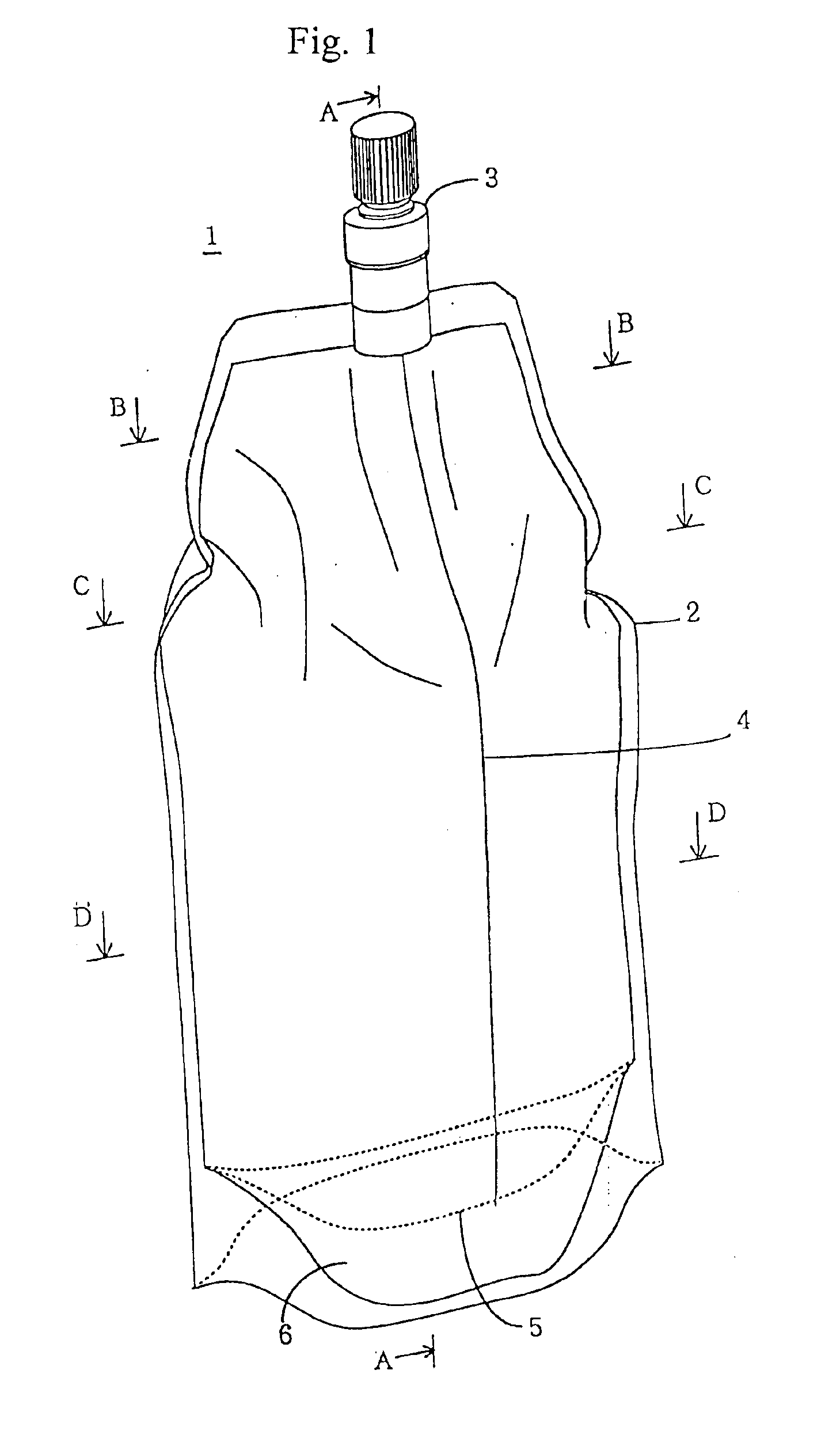
FIG. 1 is a perspective view showing the invention. A self-standing container 1 is formed of a soft sheet by an ordinary method into a stand pouch and is constructed by forming a pouring port 3 at an upper end of a container body 2 of the soft sheet portion. Further, numeral 4 designates folds which are formed to bulge from the container body 2 and to start downward from the lower end of the pouring port 3.

In FIG. 1, the material for the container body 2 can be selected from a plastic sheet, a metallic sheet or a composite sheet composed of the former sheets. The plastic sheet is exemplified by polyethylene, polypropylene, polyester, polycarbonate or a nylon resin. The container body 2 is formed by using those soft sheet or composite sheet, by applying the two material sheets (or the body side wall sheet members) and heat-sealing their peripheries over a predetermined width, and by fusing those sheets.

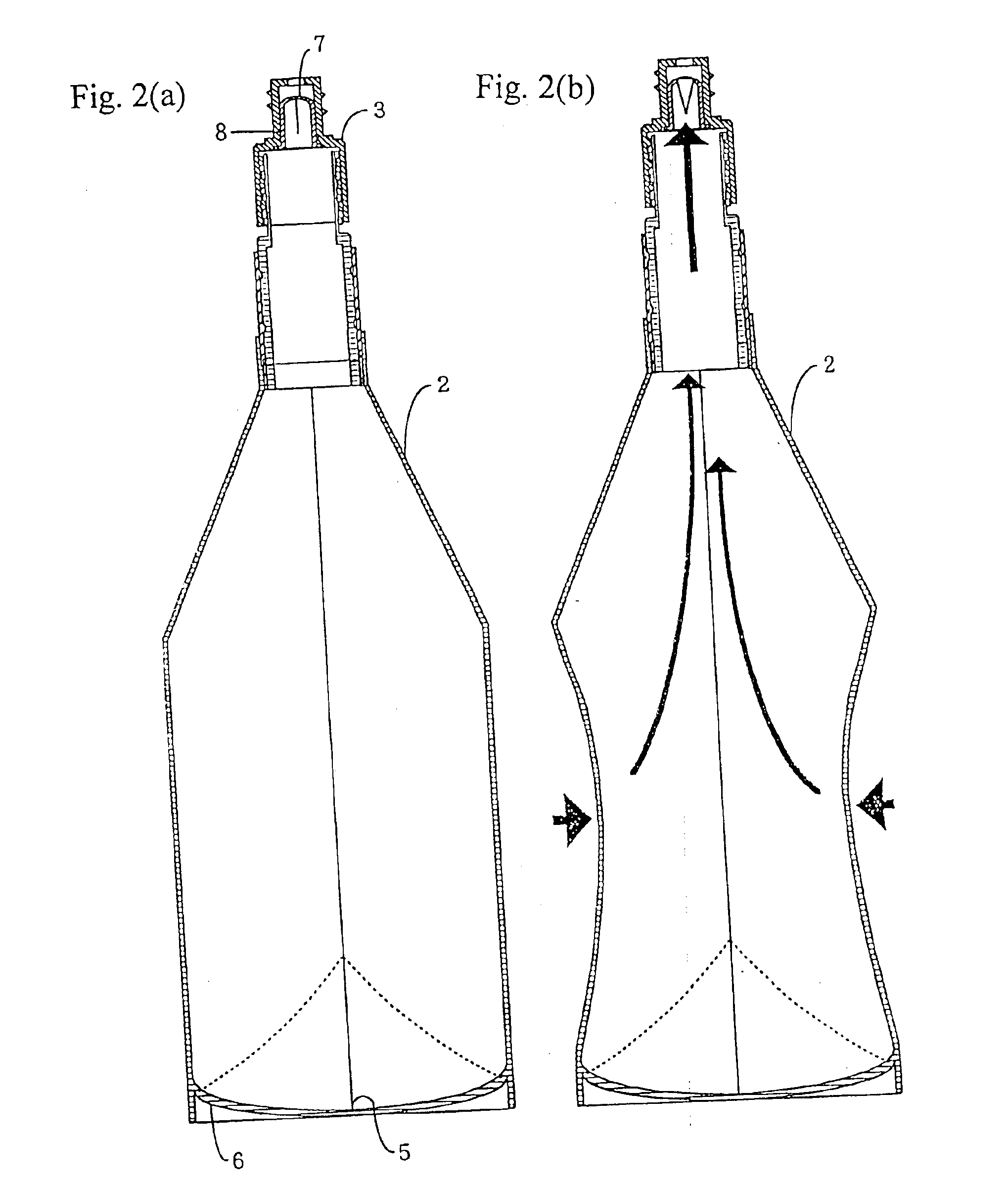
Here, the bottom of the container body 2 is fused by intervening a bottom seat mem...

second embodiment

FIGS. 11(a) to 14(d) show a self-standing bag-shaped vacuum container of the invention.

The construction of the container body other than the following flow velocity control mechanism is not different from the aforementioned container of the first embodiment. Therefore, the description of the flow velocity control mechanism features the present embodiment.

FIGS. 11(a) and (b) show a first embodiment of the flow velocity control mechanism of the present invention. FIG. 11(a) presents a longitudinal section, and FIG. 11(b) presents a sectional view B—B of an essential portion. In a screw cap 15, there is fitted a cup-shaped member 19 having a bottom forming a flow velocity control unit 20. The cup-shaped member 19 protrudes at its lower portion into the joint portion 12 and is provided in its side wall near the bottom with vent holes (passages) 21 communicating with the container body 2. These vent holes 21 are formed symmetrically with respect to a longitudinal section extending throug...


PUM

PropertyMeasurementUnit
Thicknessaaaaaaaaaa
Pressureaaaaaaaaaa

Abstract

A self-standing type bag-shaped vacuum container has a self-standing container including a wall formed of a soft sheet, a pouring port, and a check valve mounted in the pouring port. The check valve is opened to allow the migration of a content of the container when subjected to a pressure in the pouring direction, but is closed when subjected to a pressure in a filling direction, so that the inside of the container is evacuated. The self-standing container can be optimized for storing beverages or the like which are negatively effected by contact with air, because the content will be oxidized with the air. The vacuum type container will not lose its self-standing property even if the content is reduced, and can stand stably by itself.

Description

TECHNICAL FIELDThe present invention relates to a self-standing container such as a so-called “stand pouch” which can stand by itself when its bottom is expanded by being filled with a content and, more particularly, to a self-standing container which prevents the immigration of air or the like by blocking the inflow of the air with a check valve and which prevents any discharge of the content even at an accidental impact or the like.TECHNICAL BACKGROUNDIn the prior art, for the storage of beverages that have their taste deteriorated by oxidation, such as wine, sake, whiskey, fruit beverages, and vegetable juices, glass bottles have been used which are sealed with large-sized cork stoppers or screw caps. However, these glass bottles are heavy and brittle so that they are seriously troublesome to handle. It is, therefore, the current practice to use PET bottles made of plastic in place of the glass bottles.These hard containers, as represented by the PET bottles, are hardly reduced i...

Claims


Application Information

Patent Timeline
IPC IPC(8): B65D47/04B65D47/20B65D75/52B65D75/58B65D75/00
CPCB65D47/2018B65D75/5883B65D75/008
Inventor HAGIHARA, TADASHI
Owner HAGIHARA TADASHI
Why Eureka
Try Eureka