

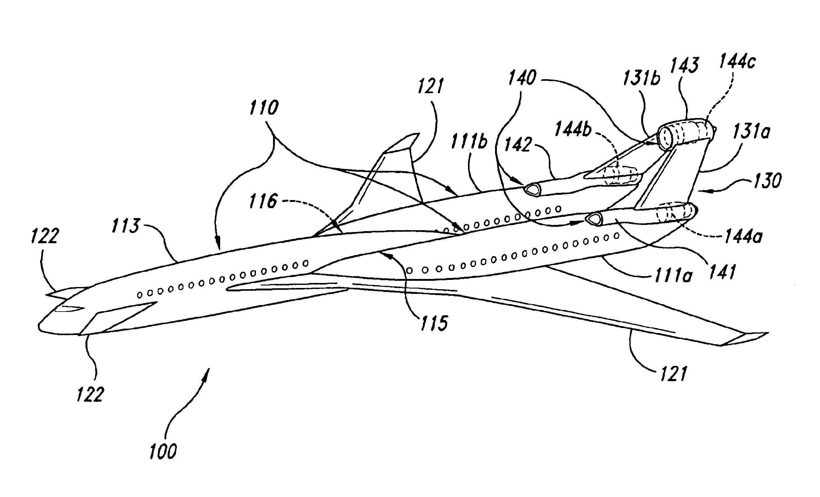
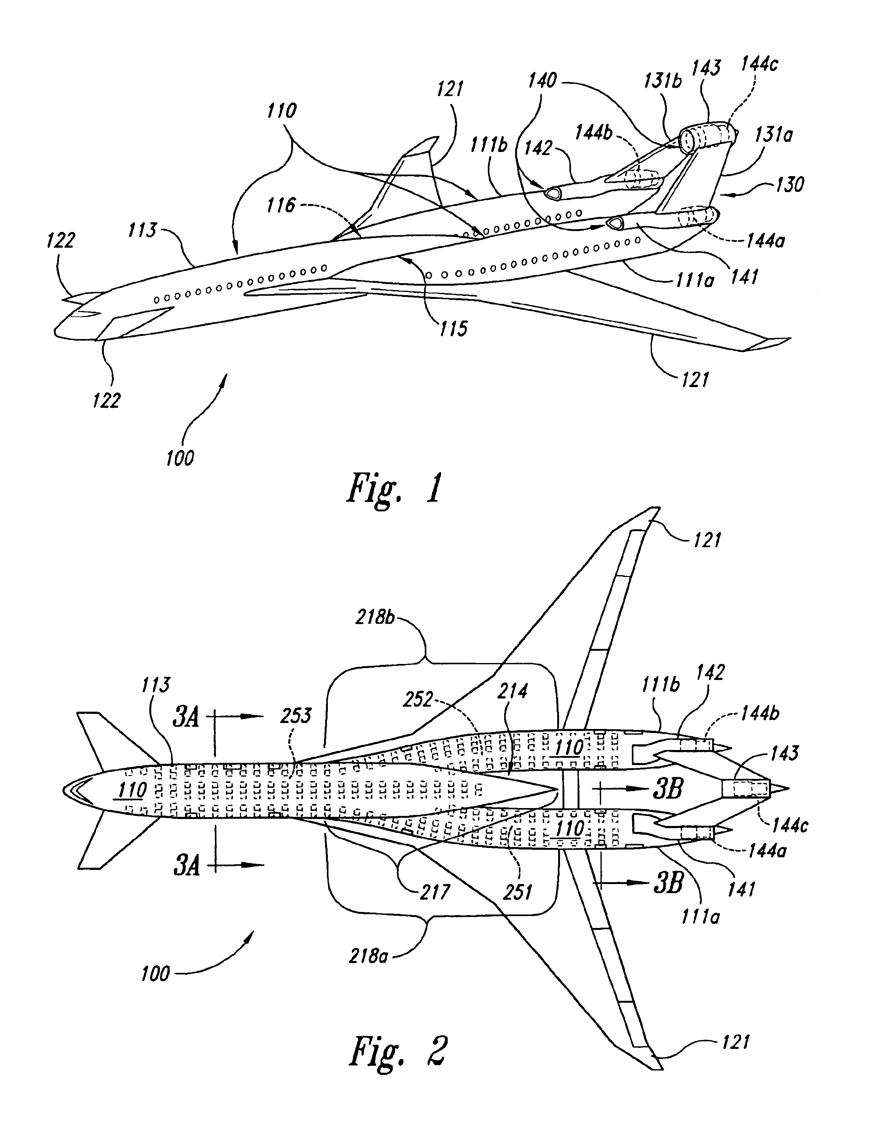
Tri-body aircraft and methods for their manufacture
a tri-body aircraft and aircraft technology, applied in the field of aircraft, can solve the problems of limiting the amount of fuel that can be carried, unable to adequately balance the aircraft, and the configuration of the aft-mounted main wing is typically nose-heavy
- Summary
- Abstract
- Description
- Claims
- Application Information
AI Technical Summary
Problems solved by technology
Method used
Image


Examples
Embodiment Construction
The following disclosure describes aircraft, such as “tri-body” aircraft, and associated methods of manufacture. Certain specific details are set forth in the following description and in FIGS. 1-7 to provide a thorough understanding of various embodiments of the invention. Those of ordinary skill in the relevant art will understand, however, that they may practice other embodiments of the invention without several of the details described below. Further, the following disclosure does not describe well-known structures and systems often associated with aircraft to avoid unnecessarily obscuring the description of the various embodiments of the invention. Any dimensions, angles, and other specifications shown in the figures are merely illustrative of particular embodiments of the invention. Accordingly, other embodiments of the invention can have other dimensions, angles, and specifications without departing from the spirit or scope of the present invention.
In the drawings, identical ...
PUM
 Abstract
Description
Claims
Application Information