Filter plate of a filter press
a filter plate and press technology, applied in the direction of filtration separation, separation processes, manufacturing tools, etc., can solve the problems of comparatively high working effort when replacing filter cloths, large differences in pressure levels of adjacent chambers, and filter cloths having to be fixed to filter plates, so as to achieve the effect of less cost and simple manufacturing
- Summary
- Abstract
- Description
- Claims
- Application Information
AI Technical Summary
Benefits of technology
Problems solved by technology
Method used
Image

Examples
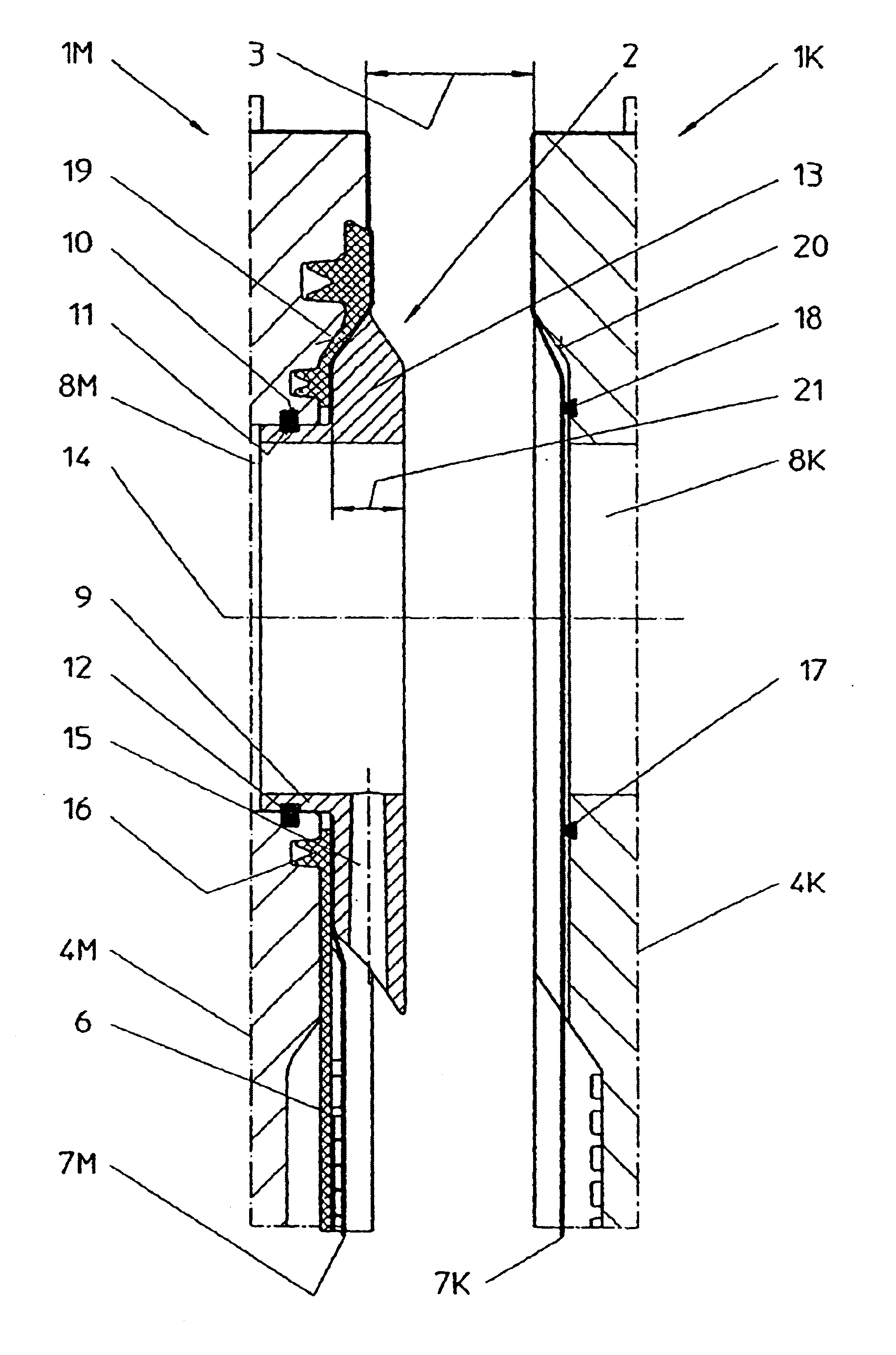
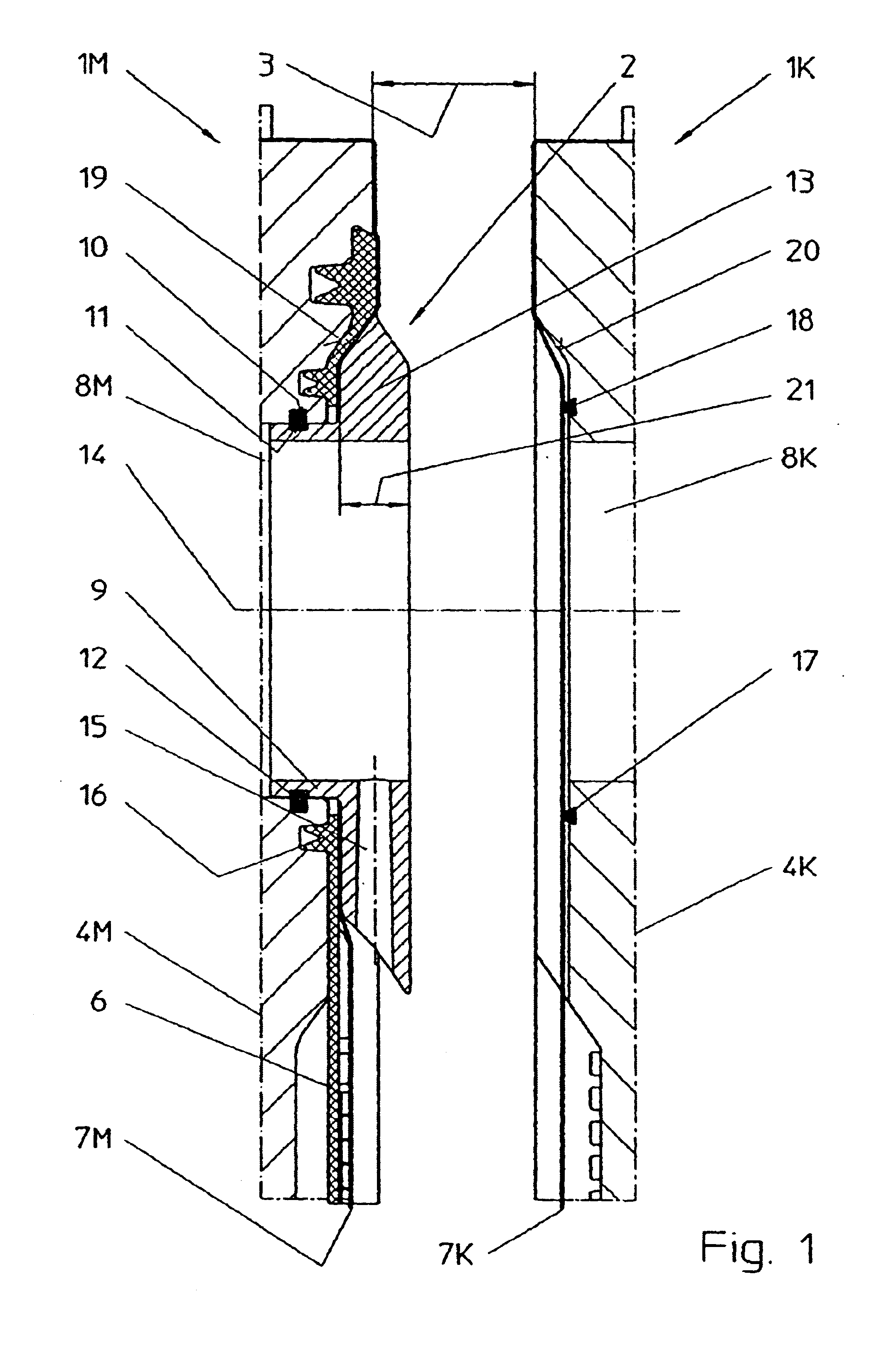
first embodiment
All other features of the first embodiment described in FIGS. 1 through 3 are maintained in the alternative version shown in FIGS. 4 and 5.
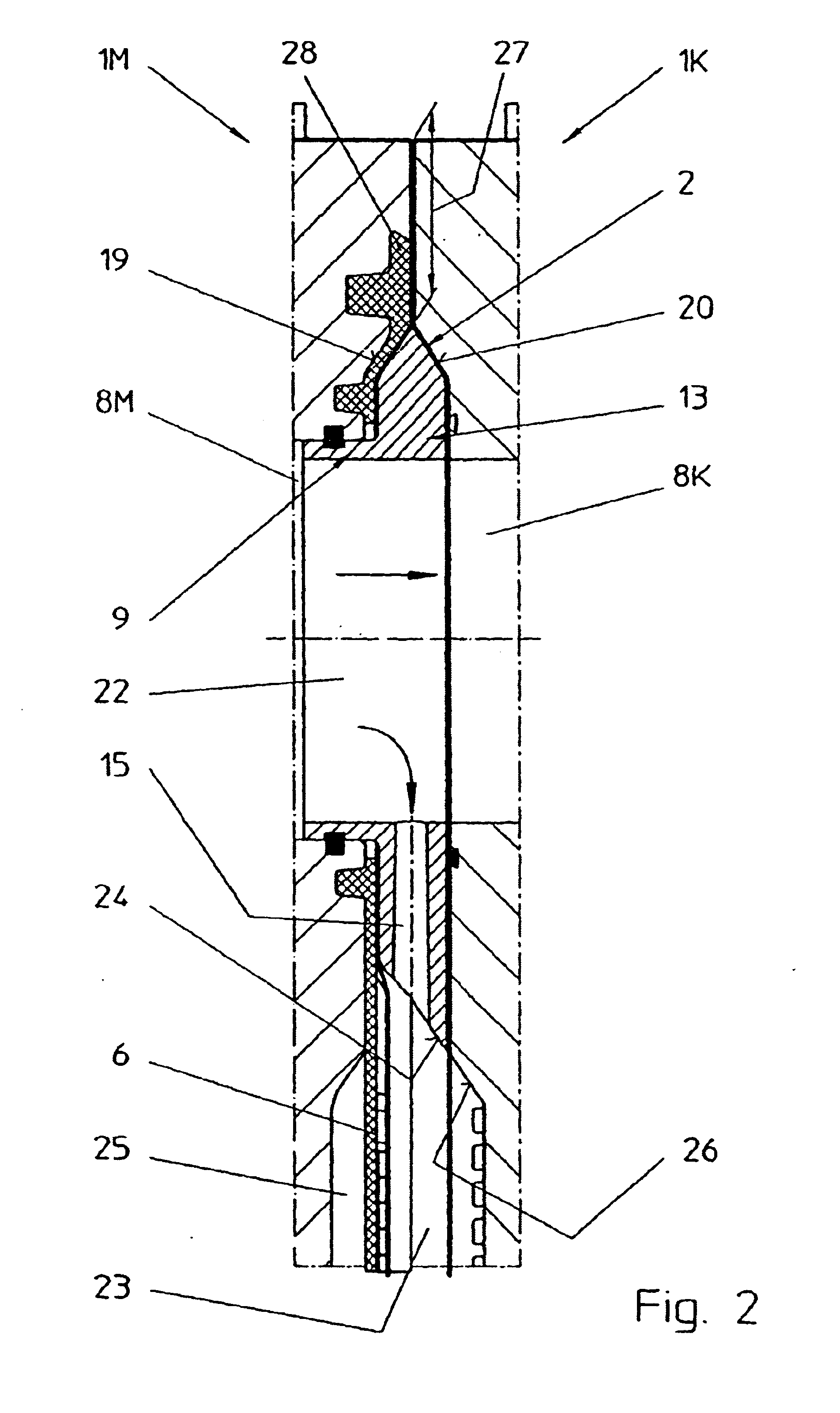
FIG. 6 shows a front view of the diaphragm plate 1M which in contrast with the illustration in FIG. 3 is shown in its entirety. It can be seen that the filling element 2 is arranged inside the circumferential sealing edge 27, but outside the actual plate face 37 which is used as the active filter surface marked by vertical lines in FIG. 6. The displacement of the filling element 2 to the outside of the plate face is made possible by the joining piece 5 which projects in an ear-like shape from the otherwise rectangular base surface of the plate. The plate sealing edge extends even in the region of the joining piece 5 on the outer edge of the diaphragm plate 1M to embrace or surround the filling element 2 from the top and lateral directions. When the filter plate package is closed, the passage bores 8M and 8K in the filter plates 1M and 1K form a c...
PUM
| Property | Measurement | Unit |
|---|---|---|
| Temperature | aaaaa | aaaaa |
| Temperature | aaaaa | aaaaa |
| Molar density | aaaaa | aaaaa |
Abstract
Description
Claims
Application Information
 - R&D
- Intellectual Property
- Life Sciences
- Materials
- Tech Scout
- Unparalleled Data Quality
- Higher Quality Content
- 60% Fewer Hallucinations
Browse by: Latest US Patents, China's latest patents, Technical Efficacy Thesaurus, Application Domain, Technology Topic, Popular Technical Reports.
© 2025 PatSnap. All rights reserved.Legal|Privacy policy|Modern Slavery Act Transparency Statement|Sitemap|About US| Contact US: help@patsnap.com