Low profile push-pull magnetic vibrating apparatus

a magnetic vibrating and low-profile technology, applied in electrical equipment, mechanical energy handling, dynamo-electric machines, etc., can solve the problems of high mechanical profile, unsuitable for a low-profile application, and not well-suited to withstand body weigh

Inactive Publication Date: 2005-02-08
MORIYASU BARBARA JUNE
View PDF6 Cites 25 Cited by
  • Summary
  • Abstract
  • Description
  • Claims
  • Application Information

AI Technical Summary

Benefits of technology

An ultra-low profile vibrating transducer, particularly suited for floor mat applications using an “I” core coil in th

Problems solved by technology

While such vibrating pads are effective in seat cushion format, they are not well suited to withstand body weight as in

Method used


Image

  • Low profile push-pull magnetic vibrating apparatus
  • Low profile push-pull magnetic vibrating apparatus
  • Low profile push-pull magnetic vibrating apparatus

Examples


Embodiment Construction

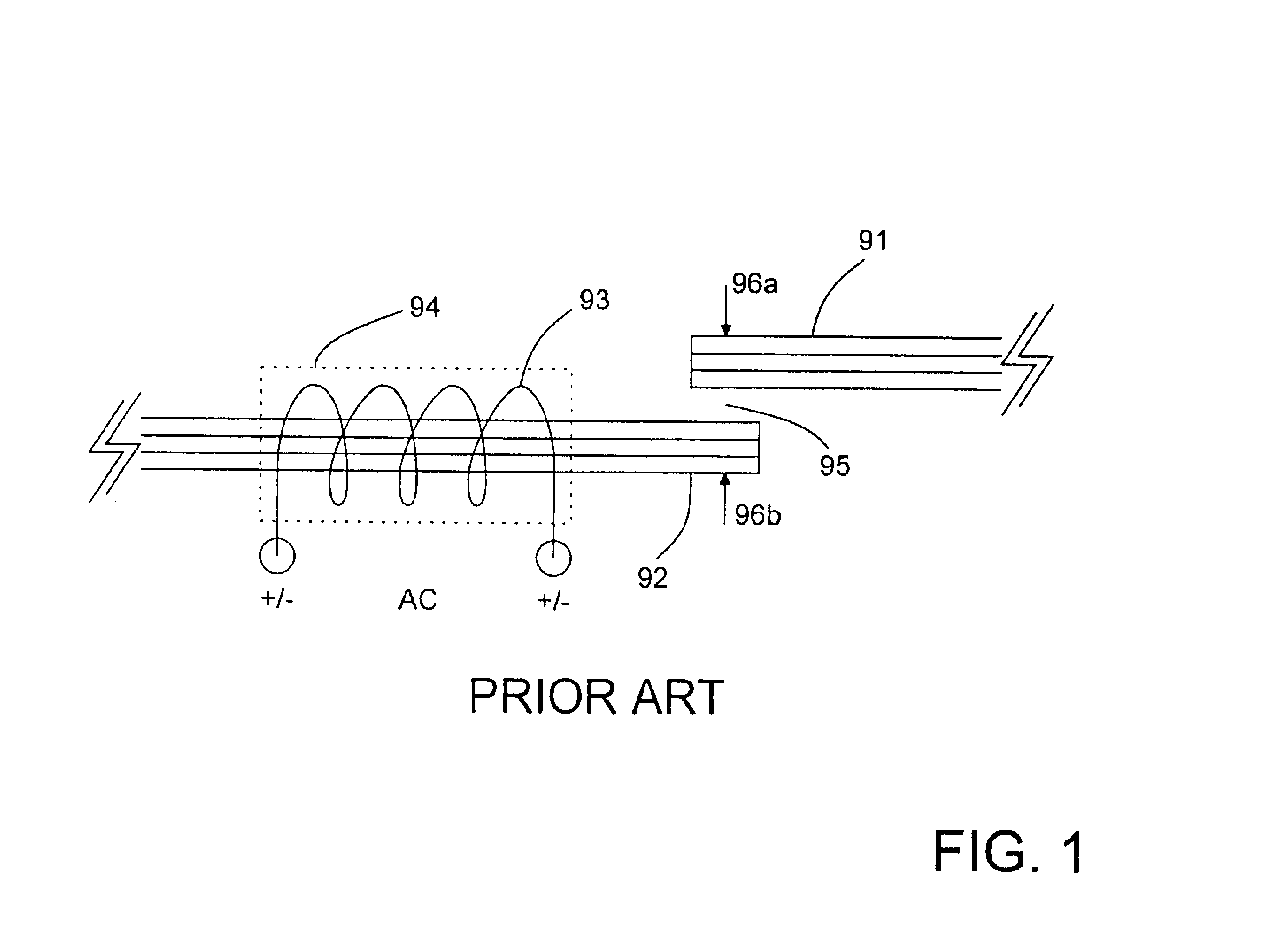
FIG. 1 is an illustration of a conventional single ended pull only drive to create a vibrating motion. The conventional vibrating transducer, according to prior arts, typically creates only pull action regardless of positive or negative electrical drive to the coils.

Vibrators, according to prior art, are typically in the of a form of a relay coil and attached flexible lever or “C” core 92, with coil 93 and an “I” core laminate 91 attached to “C” core (not shown) to form complete magnetic field (not shown) with spring loaded or elastomer 95 (not shown) spacer between “C” core and “I” core.

While “C”&“I” core can cover a large area, several limitations exist. One fundamental limitation is when the electrical signal is applied. The magnetic forces 96a and 96b can only attract each end of the magnetic pole, producing only a contractive force.

When a signal is applied, either positive or negative, the cores pull toward each other and release when the signal is zero. Polarity of force is al...


PUM


Abstract

An ultra-low profile vibrating transducer, particularly suited for floor mat and ultra thin vibrating pad and multimedia tactical feedback applications, using an “I” core coil in the center and permanent magnets positioned at both ends of the “I” core to create balanced push-pull vibrating actions. Mounting methods to effectively transfer energy to the users while withstanding user's body weight. “I” core coil may be driven by AC power, pulsed and/or DC power or audio power. Elastomeric supports are configured to provide rotational leverage action to further enhance the vibrating effectiveness.

Description

BACKGROUND OF THE INVENTIONA vibrating apparatus to be used as vibrating transducer for low profile floor mat application must meet two major obstacles. One, it must be low profile and, second, it must withstand direct body weight directly above such device without collapsing.Various vibrating apparatuses, using prior arts, have been used in vibrating massaging devices. Massage pads typically contain eccentric small motors sandwiched between the top soft foam and bottom soft foam to create vibrating massage action to a user. While such vibrating pads are effective in seat cushion format, they are not well suited to withstand body weight as in a floor mat application.Geared rotating cam action motors are used for footrest applications. However, they require high mechanical profile and are not suited for a low profile application.A relay type vibrator typically has a magnetic coil and leaf spring-like magnetic laminate that is placed above the coil with an air gap. Since it requires s...

Claims


Application Information

Patent Timeline
IPC IPC(8): H02K33/18
CPCH02K33/18
Inventor MORIYASU, HIRO
Owner MORIYASU BARBARA JUNE
Why Eureka
Try Eureka