Electromagnetic formed contact surface

a contact surface and electromagnet technology, applied in the direction of magnets, relays, magnetic bodies, etc., can solve the problems of noisy electromagnets, unstable electromagnets, and expensive operation, and achieve the effect of reducing nois

Inactive Publication Date: 2005-02-08
SIEMENS ENERGY & AUTOMATION INC
View PDF5 Cites 12 Cited by
  • Summary
  • Abstract
  • Description
  • Claims
  • Application Information

AI Technical Summary

Benefits of technology

In accordance with the invention, an electromagnetically actuable device has electromagnets with formed contact surfaces to minimize noise.

Problems solved by technology

This in combination with other variations in contact surfaces can produce a noisy device.
This is a costly operation which must be done within tight limits and can have poor results.
Small warping of either magnetic part can still result in an unstable and thus noisy electromagnet.

Method used


Image

  • Electromagnetic formed contact surface
  • Electromagnetic formed contact surface
  • Electromagnetic formed contact surface

Examples


Embodiment Construction

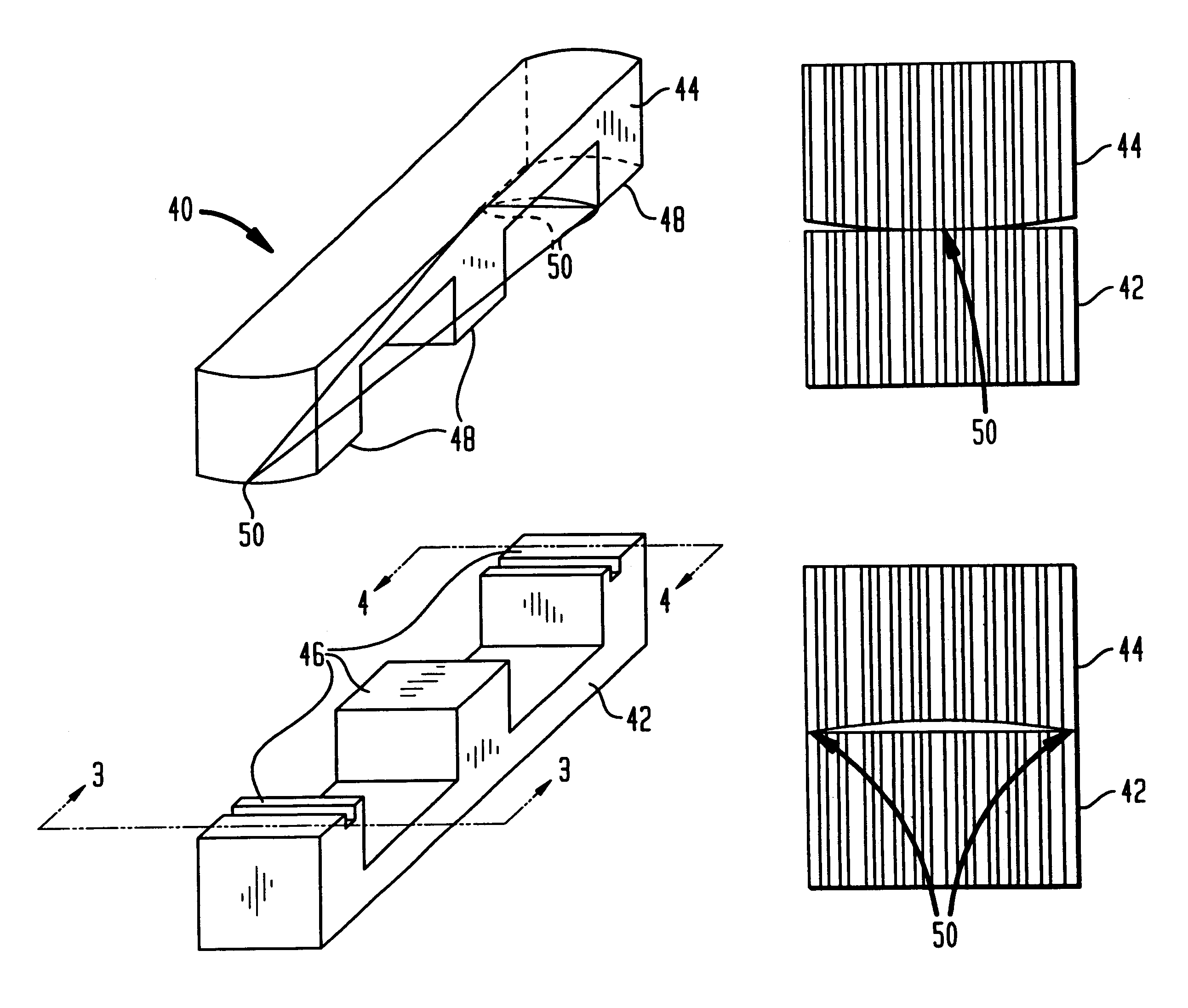
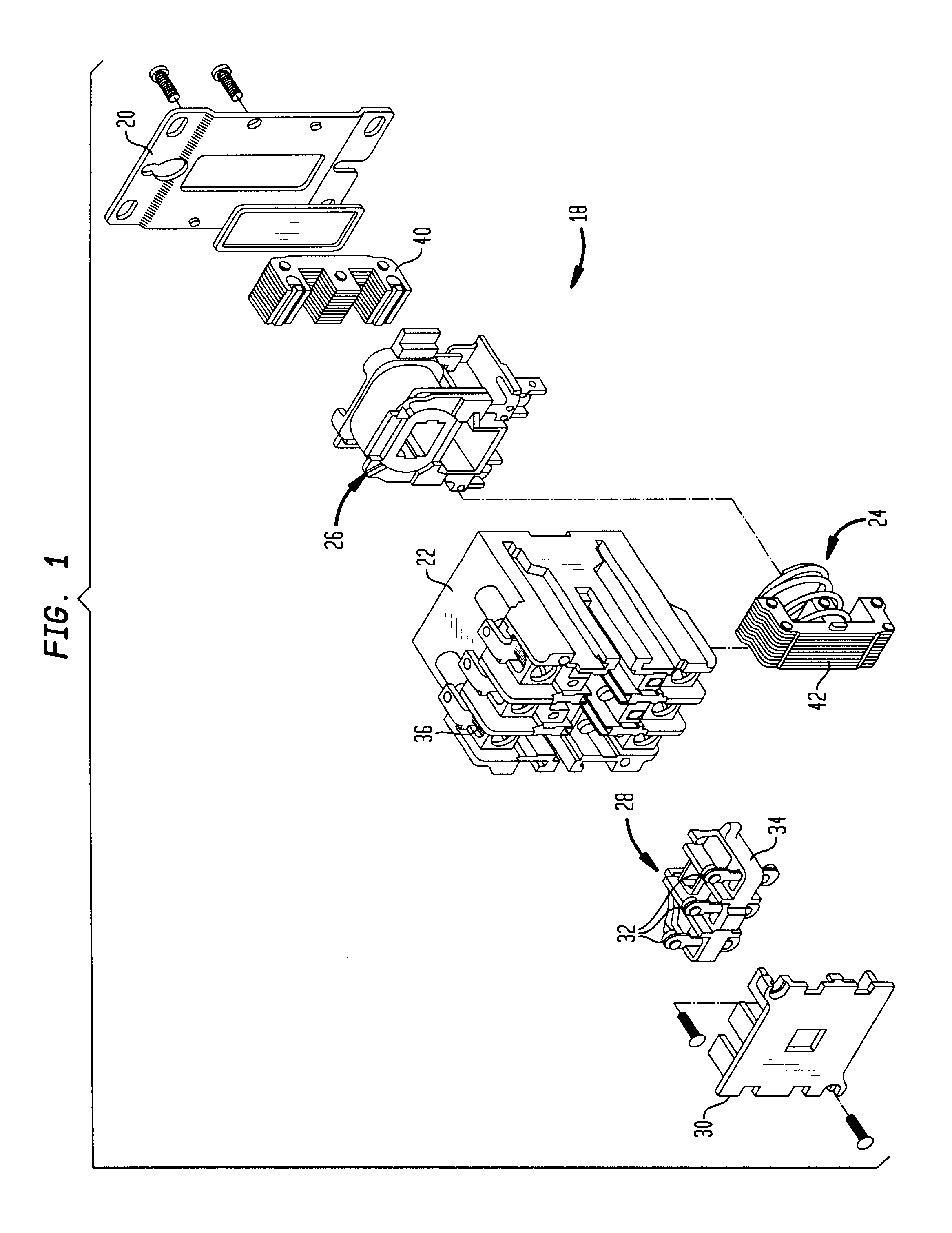
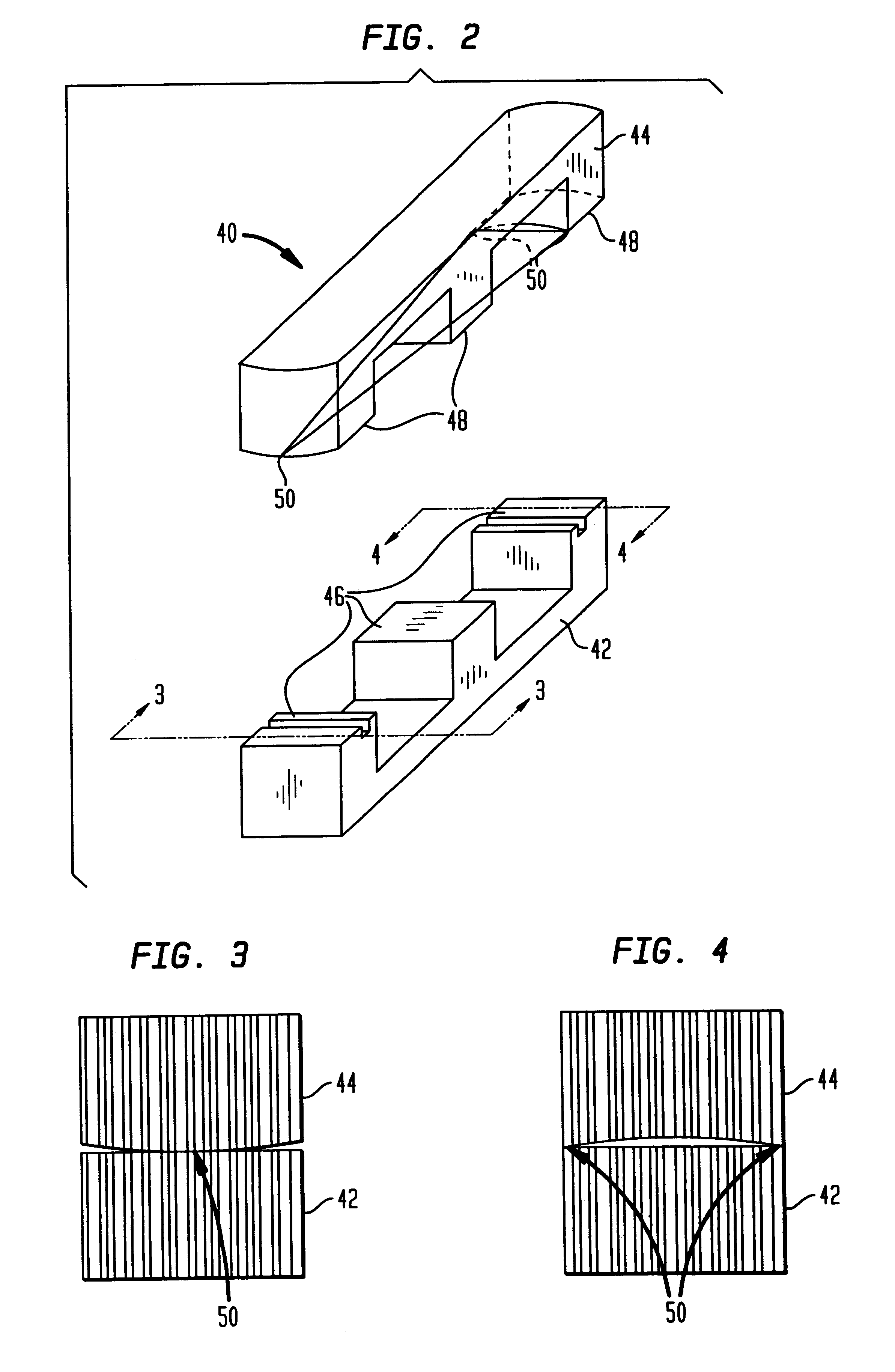
Referring initially to FIG. 1, an electromagnetically actuable device in the form of an electrical contactor 18 is illustrated in exploded form. The contactor 18 includes a base 20, a housing 22, an electromagnet 24, a coil 26 an actuator assembly 28 and a cover plate 30. The electromagnet 24 includes a magnetic core 40 and an armature 42. The housing 22 is mounted to the base and encloses the coil 26 and the magnetic core 40. The magnetic core 40 is fixedly mounted in the housing 22. The magnetic core 40 is made of laminated magnetic steel, as is well known. The coil 26 includes a conventional bobbin, winding and terminal assembly and is located within the housing 22 and on the magnetic core 40. The armature 42 is also of laminated magnetic steel and is associated with movable contacts 32 carried on a contact carrier 34 moveable mounted in the housing 22. The housing 22 also supports stationary contacts 36 positioned in proximity with the moveable contacts 32.

When the coil 26 is en...


PUM


Abstract

An electromagnetically actuable device includes a base. A magnetic core is fixedly mounted to the base. An armature is movably mounted to the base proximate the magnetic core. A coil is fixedly mounted to the base and is selectively energized to draw the armature to the magnetic core. The armature and magnetic core have mating surfaces adapted to provide three contact areas in a triangular configuration to provide minimal magnetic air gap and a stable interface when the coil is energized.

Description

TECHNICAL FIELD OF THE INVENTIONThis invention relates to electromagnetically actuable devices and, more particularly, to electromagnet formed contact surfaces.BACKGROUND OF THE INVENTIONA conventional electromagnetically actuable device has a magnetic core proximate an armature. A coil is selectively energized to draw the armature to the magnetic core. The device may be a solenoid, a contactor, a motor starter, or the like. The armature is operatively associated with a movable device such as movable contacts or an actuator. In many instances the coil is selectively energized from an AC power source. With AC-operated electromagnets, elimination or control of noise is a prime concern. To minimize noise the surface interface of the magnetic core and armature of each device must be matched to provide minimal magnetic “air gap” and a stable interface surface. The minimal air gap assures sufficient force to prevent movement and the stable surface interface prevents movements due to the w...

Claims


Application Information

Patent Timeline
Patent Type & Authority Patents(United States)
IPC IPC(8): H01H50/16H01H50/22
CPCH01H50/163H01H50/22
Inventor SMITH, RICHARD G.
Owner SIEMENS ENERGY & AUTOMATION INC
Why Eureka
Try Eureka