Crossover filter system and method

a filter system and cross-over technology, applied in the field of cross-over filters, can solve the problems of increasing group delay, inability to achieve a recombined amplitude response, inability to roll off the response to each electroacoustic transducer quickly enough, etc., to improve the attenuation of out of band signals, improve the amplitude response, and improve the effect of amplitud

Inactive Publication Date: 2005-02-08
IMMERSION TECH PROPERTY
View PDF7 Cites 65 Cited by
  • Summary
  • Abstract
  • Description
  • Claims
  • Application Information

AI Technical Summary

Benefits of technology

The present invention proposes a new class of crossover filters suitable for, inter alia, crossing over between pairs of loudspeaker transducers. The crossover filters of the present invention may include a pair of filters such as a high pass and a low pass filter. Each filter may have an amplitude response that may include a notch or null response at a frequency close to or in the region of the crossover frequency. A notch or null response above the crossover frequency in the low pass filter and below the crossover frequency in the high pass filter may provide a greatly increased or steeper roll off for each filter of the crossover for any order of filter. Notwithstanding the notch or null response the amplitude responses of the pair of filters may be arranged to add together to produce a combined output that is substantially flat or constant in amplitude at least across the region of the crossover frequency. Benefits of such an arrangement include improved amplitude response and improved out of band signal attenuation close to the crossover frequency for each band.

Problems solved by technology

Common shortcomings of prior art crossover filters include an inability to achieve a recombined amplitude response which is flat or constant across the one or more crossover frequencies and / or an inability to roll off the response to each electroacoustic transducer quickly enough, particularly at the low frequency side of the crossover frequency.
However a disadvantage of this approach is that it increases group delay.

Method used


Image

  • Crossover filter system and method
  • Crossover filter system and method
  • Crossover filter system and method

Examples


Embodiment Construction

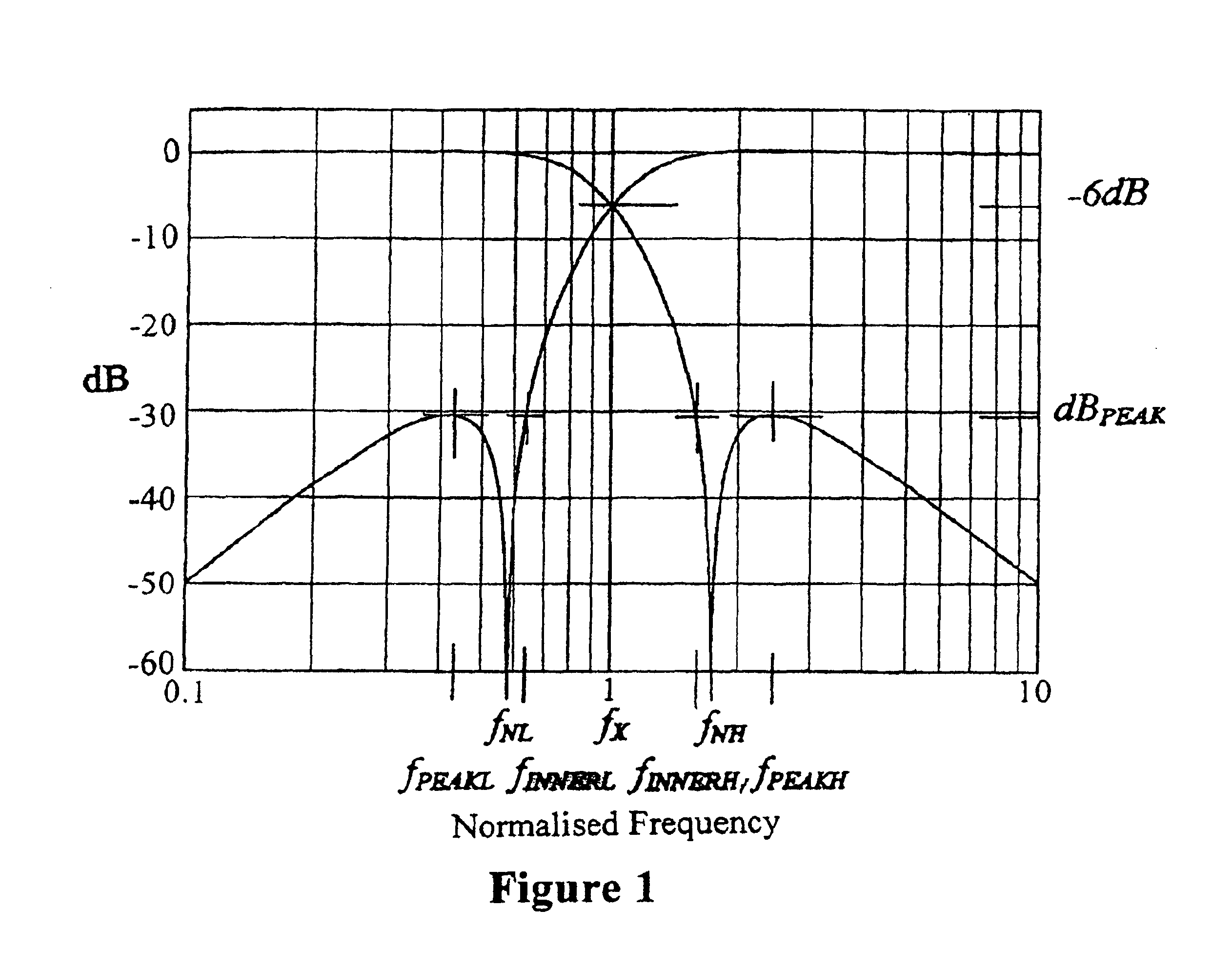
The generalised responses of even-order notched crossovers are shown in FIG. 1. FNL is the lower null centre frequency for the high pass filter, FNH is the upper null centre frequency for the low pass filter, FPEAKH is the upper peak frequency for the low pass filter, FINNERL is the highest frequency at which the output of the high pass filter equals the peak value below the null for the high pass filter, FINNERH is the lowest frequency at which the output of the low pass filter equals the peak value above the null for the low pass filter and FX is the crossover or transition frequency. The in-band response of each filter rises at first to a small peak at the frequency of the out-of-band peak of the other filter. It then falls back to reference 0 dB level at the other filter's notch frequency, and onwards to −6.0 dB at the transition frequency fX.

The response falls to a null at its fN, then rises to dBPEAK at fPEAK before falling away again at extreme frequencies at a rate, for an n...


PUM


Abstract

A filter system including a low pass filter having a response which rolls off towards a crossover frequency and a high pass filter having a complementary response which rolls off towards the crossover frequency. The responses are arranged such that the combined response of the filters is substantially constant in amplitude at least in the region of the crossover frequency. The response of the low pass filter is defined by a low pass complex transfer function having a first numerator and a first denominator. The response of the high pass filter is defined by a high pass complex transfer function having a second numerator and a second denominator. The desired response is obtained when the second denominator is substantially the same as the first denominator and the sum of the first and second numerators has substantially the same squared modulus as the first or second denominator.

Description

BACKGROUND OF THE INVENTIONThe present invention relates to crossover filters suitable for dividing wave propagated phenomena or signals into at least two frequency bands.The phenomena / signals are to be divided with the intention that recombination of the phenomena / signals can be performed without corrupting amplitude integrity of the original phenomena / signals.The present invention will hereinafter be described with particular reference to filters in the electrical domain. However, it is to be appreciated that it is not thereby limited to that domain. The principles of the present invention have universal applicability and in other domains, including the electromagnetic, optical, mechanical and acoustical domains. Examples of the invention in other domains are given in the specification to illustrate the universal applicability of the present invention.Crossover filters are commonly used in loudspeakers which incorporate multiple electroacoustic transducers. Because the electroacou...

Claims


Application Information

Patent Timeline
Patent Type & Authority Patents(United States)
IPC IPC(8): H04R3/12H04R3/14
CPCH04R3/14
Inventor THIELE, ALBERT NEVILLE
Owner IMMERSION TECH PROPERTY
Why Eureka
Try Eureka