Four-wheel-drive automatic swimming pool cleaner

a technology of automatic cleaning and automatic cleaning, which is applied in the direction of gymnasium, construction, buildings, etc., can solve the problems of insufficient attention to shortcoming, failure of certain kinds of cleaners to provide complete cleaning coverage, and difficulty in obtaining complete coverage, etc., to achieve excellent cleaning ability, excellent traction, and excellent ability to traverse pool surfaces.

Inactive Publication Date: 2005-02-15
HAYWARD IND INC
View PDF12 Cites 167 Cited by
  • Summary
  • Abstract
  • Description
  • Claims
  • Application Information

AI Technical Summary

Benefits of technology

Another object of the invention is to provide an improved wheeled automatic swimming pool cleaner of the water-driven type which has excellent traction in a variety of situations.
Still another object of the invention is to provide an improved wheeled automatic swimming pool cleaner of the water-driven type which has excellent ability to traverse pool surfaces of different types and hard-to-reach pool areas.
Yet another object of the invention is to provide an improved automatic pool cleaner of the water-driven type exhibiting excellent cleaning ability.
Another object of the inve

Problems solved by technology

Various problems and shortcoming exist in such prior devices.
Among the problems and shortcomings not adequately addressed are failures of certain kinds of cleaners to provide complete cleaning coverage.
Obtaining complete coverage is particularly difficult or problematic for swimming pools having certain kinds of surfaces, surface shapes or obstacles.
Complete coverage, and thus satisfactory cleaning, are difficult to obtain when the pumping pressure generated by the pump is weak, such that the driving force of a pool cleaner is seriously diminished.
Various automatic pool cleaners of the prior art have insufficient speed and strengt

Method used


Image

  • Four-wheel-drive automatic swimming pool cleaner
  • Four-wheel-drive automatic swimming pool cleaner
  • Four-wheel-drive automatic swimming pool cleaner

Examples


Embodiment Construction

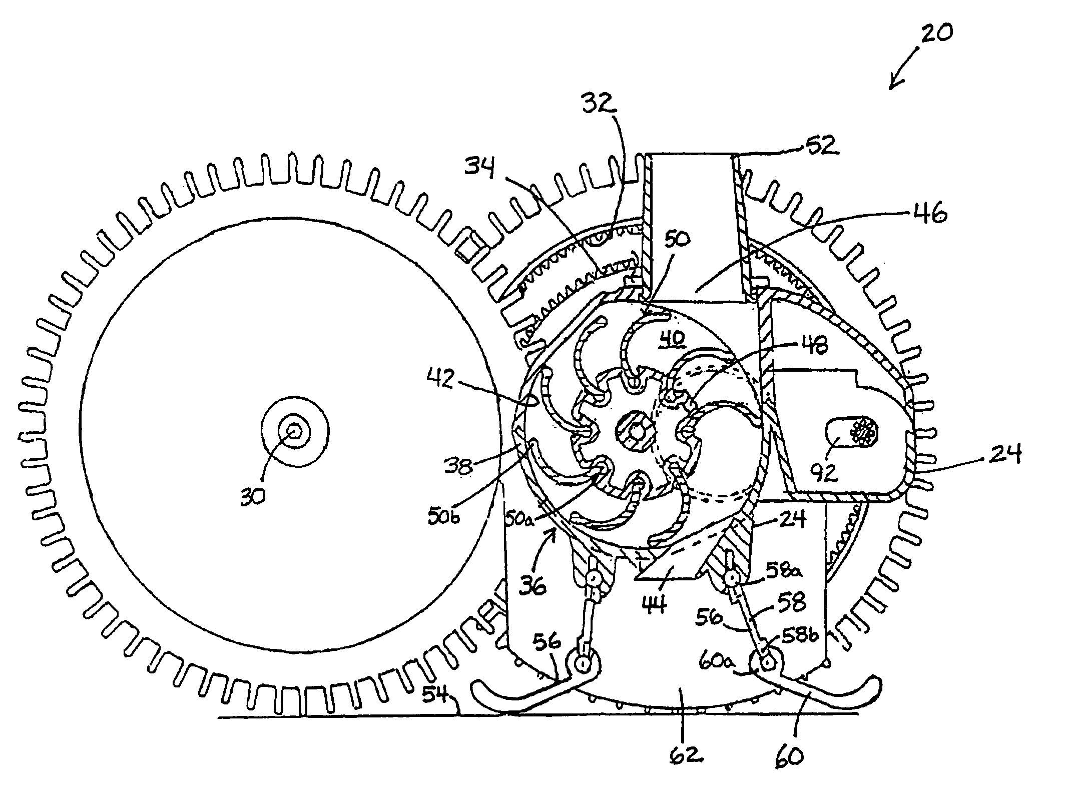
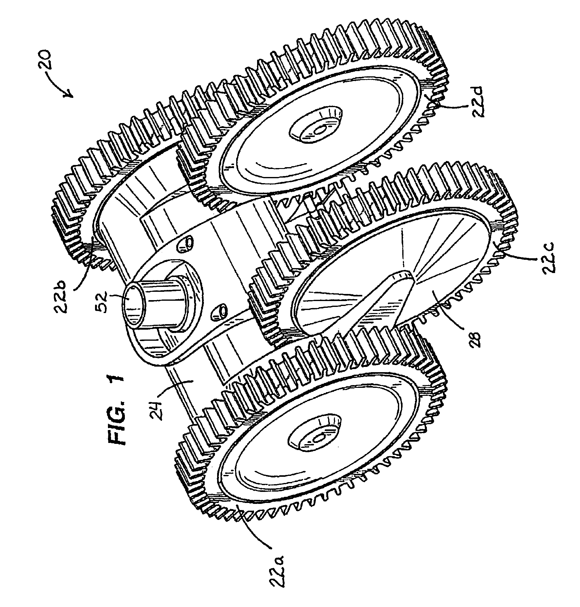
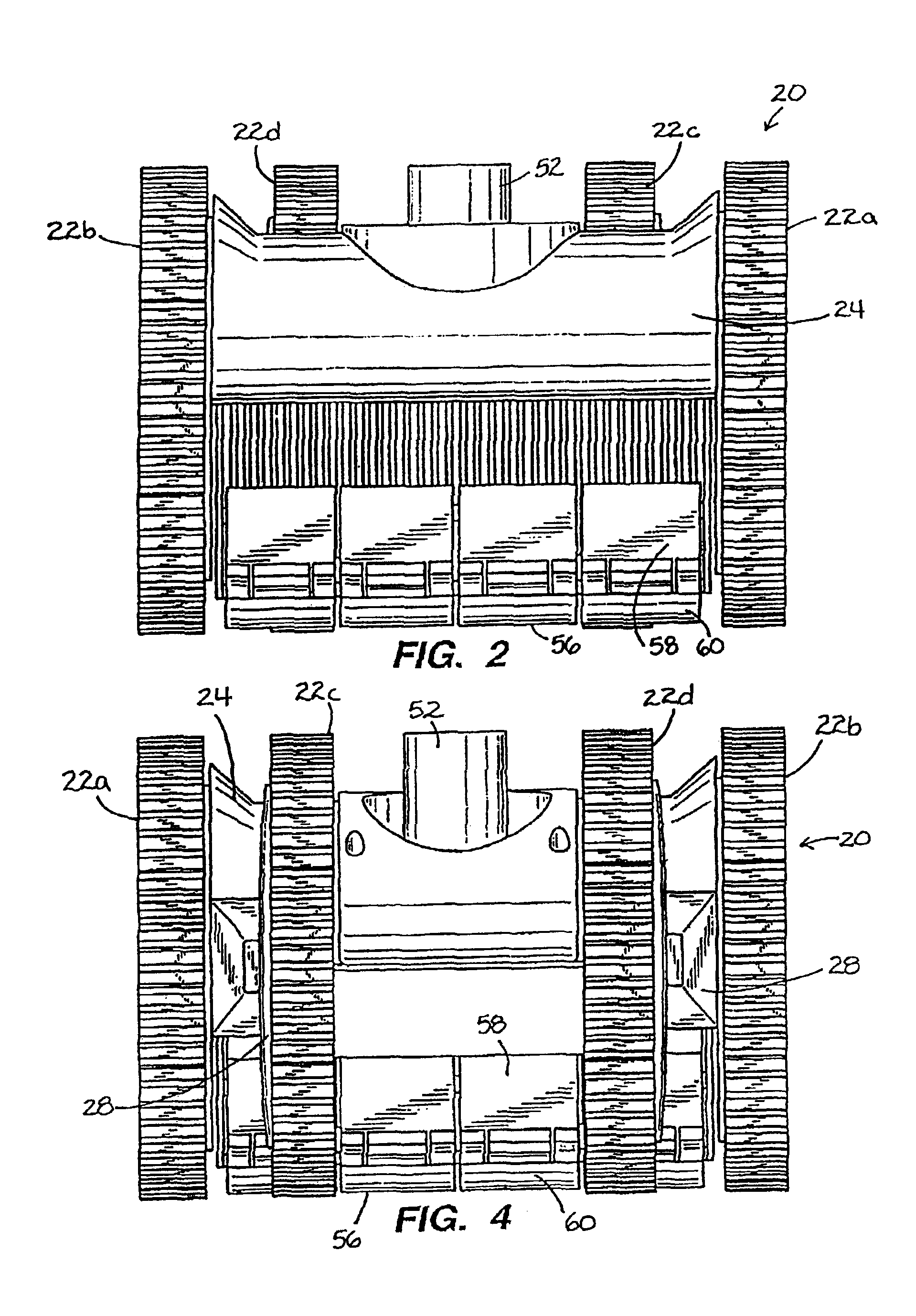
FIGS. 1-9 illustrate a preferred automatic swimming pool cleaner 20 in accordance with this invention. Pool cleaner 20 has four identical drive wheels marked by numeral 22, including left front drive wheel 22a, right front drive wheel 22b, and left and right rear drive wheels 22c and 22d. All four drive wheels are driven to provide forward movement of pool cleaner 20. Rear drive wheels 22c and 22d are driven by separate linkages from front wheels 22a and 22b, respectively.

Left front drive wheel 22a, which is normally driven in a forward direction, is periodically temporarily driven in a reverse direction. When this occurs, left rear drive wheel 22c is also driven in a reverse direction by virtue of the linkage between drive wheels 22a and 22c. During such brief intermittent periods of reverse rotation, the direction of travel of pool cleaner 20 changes. This steering function, together with the power provided by four-wheel drive of this invention, provides excellent cleaning coverag...


PUM


Abstract

A four-wheel pool cleaner (20) motivated by water flow to move along a pool surface, and having: a body (24); the four wheels rotatably mounted thereon and including two sets of two wheels (22) each, one wheel of each set on each side; a drive mechanism (36) in position to be moved by water flow and having a rotatable drive member (76); a drive train extending to the first wheel set (22a, b) and to the second wheel set (22c, d), to drive all four wheels. Preferred embodiments include: wheel-to-wheel drive links (88) along the side; a turbine (36) as drive mechanism; a pair of spaced wheelgears (32, 34), preferably integrally formed with the wheel, facilitating drive linkages and steering; a pair of end-to-end drive shafts (80, 82) joined by a coupler (84c), one shaft end (80a) being a ball joint allowing fore-and-aft movement of a drive-shaft distal end; a spring (102) and cam (100) for alternately moving that distal end between a driving position engaging one of the spaced wheelgears (32), and a steering position engaging the other of the spaced wheelgears (34); wheel treads (108) with radial fingers (110), some (110a-c) of longer length; and a segmented articulated skirt (56) to help enclose a plenum beneath the pool cleaner.

Description

FIELD OF THE INVENTIONThe present invention relates to swimming pool cleaners and, more particularly, to automatic pool cleaners driven by the flow of water therethrough for purposes of cleaning. Still more particularly, the invention relates to wheeled automatic swimming pool cleaners.BACKGROUND OF THE INVENTIONAutomatic swimming pool cleaners of the type that move about the underwater surfaces of a swimming pool are driven by many different kinds of systems. A variety of different pool cleaner drive devices in one way or another harness the flow of water, as it is drawn (or in some cases pushed) through the pool cleaner by the pumping action of a remote pump for debris collection purposes, to create forward pool cleaner movement. Some of the many kinds of water-driven automatic pool cleaners are those driven in various ways by turbines, which translate water movement into rotational motion, and those driven in various ways by oscillators, which move back and back and forth by virt...

Claims


Application Information

Patent Timeline
IPC IPC(8): E04H4/16E04H4/00
CPCE04H4/1654
Inventor RIEF, DIETER J.RIEF, MANUELA
Owner HAYWARD IND INC
Why Eureka
Try Eureka