Adjustable support brace and mounting shoe

a technology of adjustable support and mounting shoe, which is applied in the direction of machine support, building repair, application, etc., can solve the problems of lack of strong mounting footing of current bracing equipment, and achieve the effect of significantly increasing the working load of the support bra

Inactive Publication Date: 2005-02-15
DAYTON SUPERIOR CORP
View PDF7 Cites 41 Cited by
  • Summary
  • Abstract
  • Description
  • Claims
  • Application Information

AI Technical Summary

Benefits of technology

One advantage of the present invention is that the mounting shoe of the adjustable support brace is designed to utilize multiple mounting bolts. The working load of the support brace is therefore significantly increased. With the increased working load, a support system can be created for the concrete walls of a construction project utilizing fewer suppo

Problems solved by technology

Current bracing equipment lack a strong mounting footing.
Due to the strength limitations of the footings of convention

Method used


Image

  • Adjustable support brace and mounting shoe
  • Adjustable support brace and mounting shoe
  • Adjustable support brace and mounting shoe

Examples


Embodiment Construction

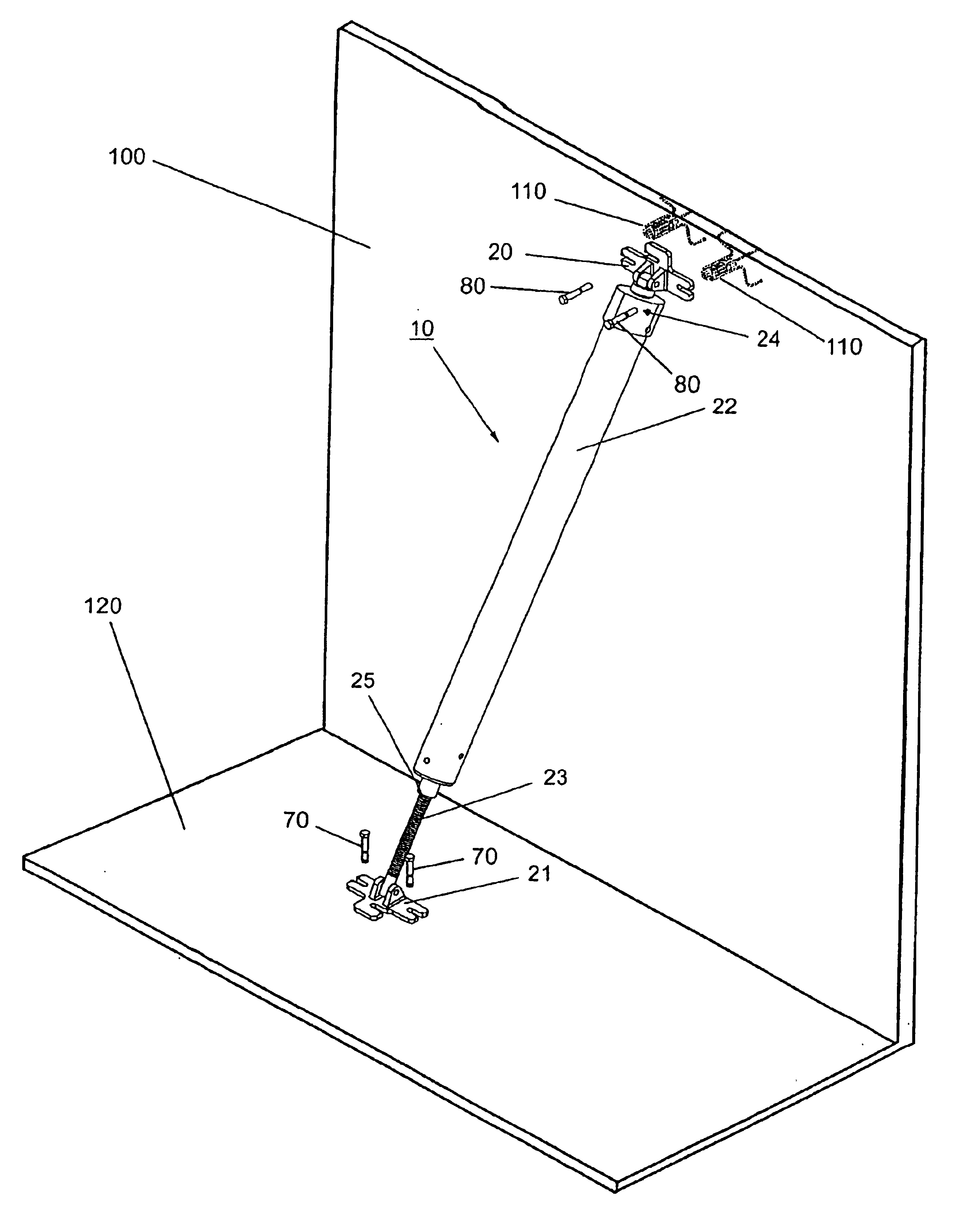
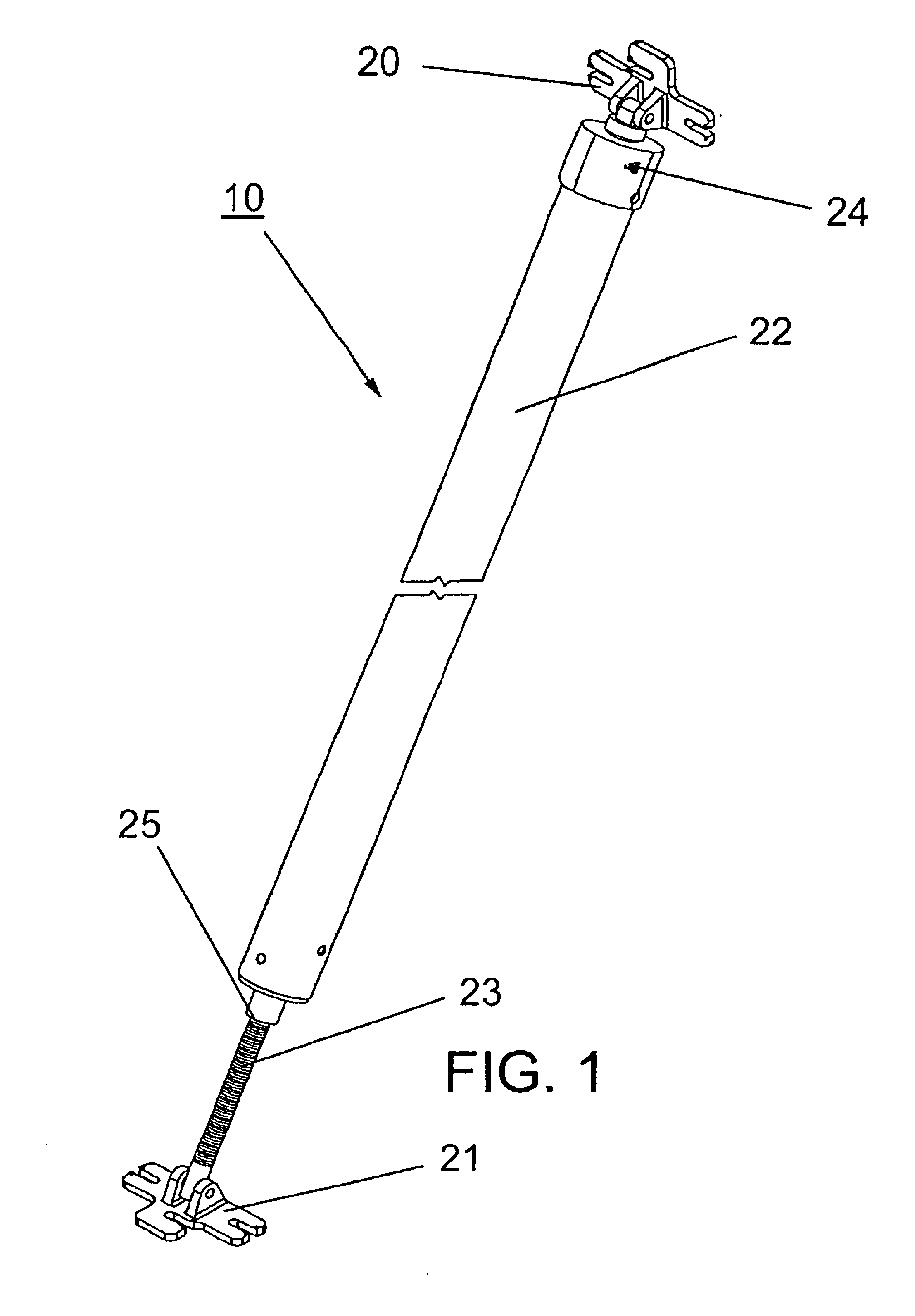
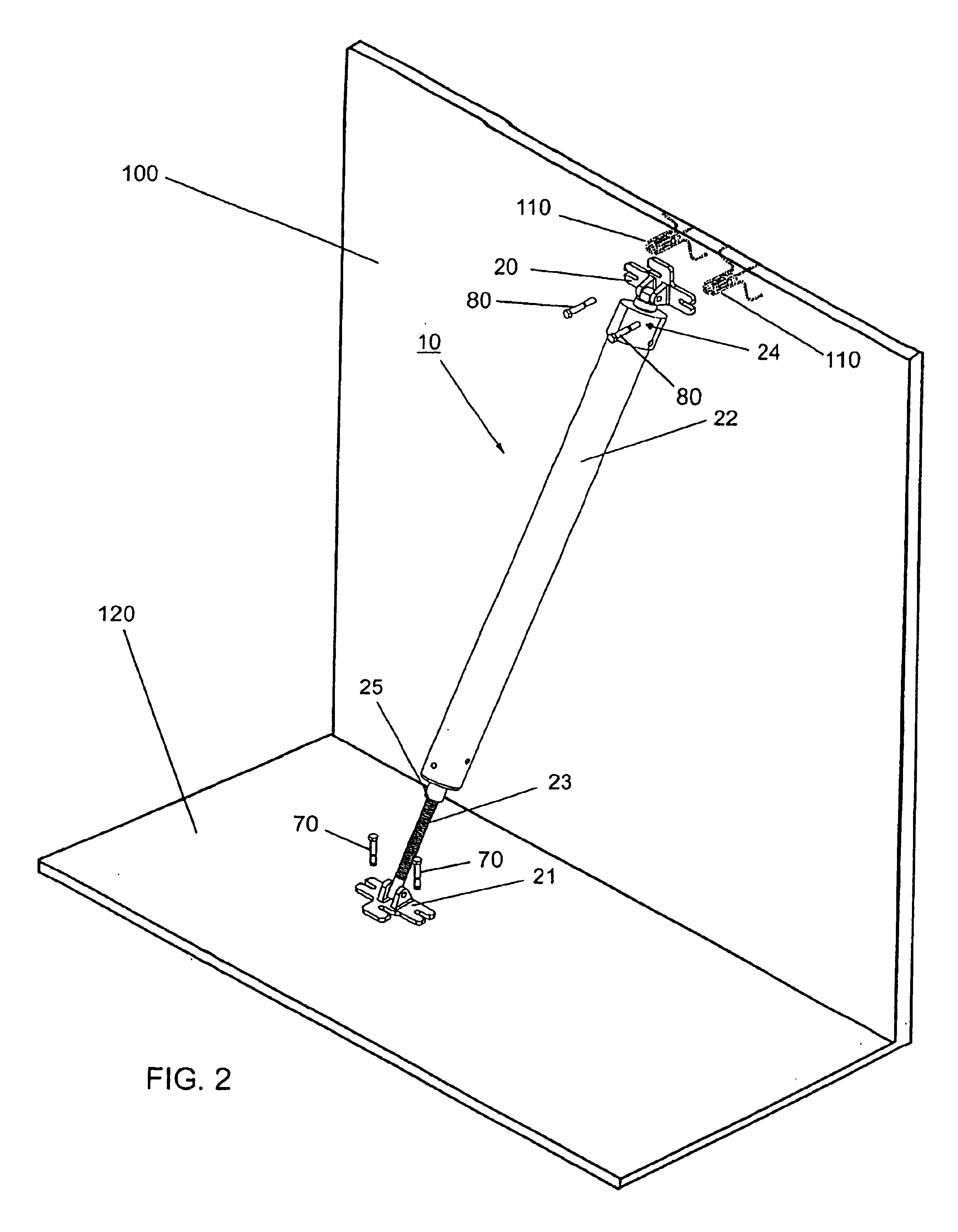
The present invention is detailed in FIGS. 1-5. One embodiment of the present invention is directed towards an adjustable support brace 10 for a pre-cast or tilt-up concrete wall 100. This aspect of the invention is detailed in FIGS. 1 and 2. The support brace 10 of the present invention comprises a first mounting shoe 20, a second mounting shoe 21, a leg member 22 having an upper and a lower end, and a threaded support screw 23. The first mounting shoe 20 is pivotally connected to a mounting cap 24 which is connected to the upper end of the leg member 22. The lower end of the leg member has an internally threaded receiving aperture 25 which extends at least partially through the length of the leg member 22. The internally threaded receiving aperture 25 receives the threaded support screw 23. The support screw 23 is pivotally connected to the second mounting shoe 21.

The use of adjustable support brace is detailed in FIGS. 2, 4 and 5. The first mounting shoe 21 is bonded to a concret...


PUM


Abstract

The present invention is directed towards an adjustable support brace for a pre-cast or tilt-up wall. The adjustable support brace comprises a wall mounting shoe, a floor mounting shoe, a leg member having an upper and a lower end, and a threaded support screw. The wall mounting shoe is pivotally connected to a mounting cap which is connected to the upper end of the leg member. The lower end of the leg member has an internally threaded receiving aperture which extends at least partially through the length of the leg member. The internally threaded receiving aperture receives the threaded support screw. The support screw is pivotally connected to the floor mounting shoe.

Description

BACKGROUND OF INVENTIONThe present invention is directed towards a mounting shoe and adjustable brace for a pre-cast or tilt-up wall.A common construction technique relating to the erection of buildings involves first fabricating horizontal panels and then tilting those panels to a vertical orientation for use as the walls of the building. Concrete wall panels are often fabricated in a horizontal position as they can be handled more easily in this position. Pre-cast concrete walls are also often transported to construction sites in a horizontal position.An important aspect of this construction technique is the need to provide bracing for the tilt-up panels while other panels and connecting structure is being erected. For this purpose, temporary braces are commonly used that extend obliquely from the panel to the adjacent floor. Even if the tilt-up panel is vertical and its weight is fully supported by the floor, the temporary brace must be sturdy enough to counteract winds, loads, o...

Claims


Application Information

Patent Timeline
IPC IPC(8): E04G21/24E04G21/26
CPCE04G21/26Y10T403/4681F16B2200/403
Inventor HANSORT, RENS
Owner DAYTON SUPERIOR CORP
Why Eureka
Try Eureka