High-density optical fiber distribution frame

An optical fiber distribution frame and high-density technology, applied in the field of communication equipment, can solve the problems of disordered wiring and inconvenient maintenance of wiring and wiring, and achieve the effects of improving uniformity, increasing the scope of use, and reducing confusion and entanglement.

Active Publication Date: 2021-11-19
SHENZHEN ADTEK TECH CO LTD
View PDF6 Cites 0 Cited by
  • Summary
  • Abstract
  • Description
  • Claims
  • Application Information

AI Technical Summary

Problems solved by technology

[0004] In view of the above-mentioned related technologies, the inventor believes that the existing distribution frame has the defect of disordered wiring, which makes it very inconvenient to maintain the wiring in the later stage, so further improvement is needed

Method used


Image

  • High-density optical fiber distribution frame
  • High-density optical fiber distribution frame
  • High-density optical fiber distribution frame

Examples


Embodiment 1

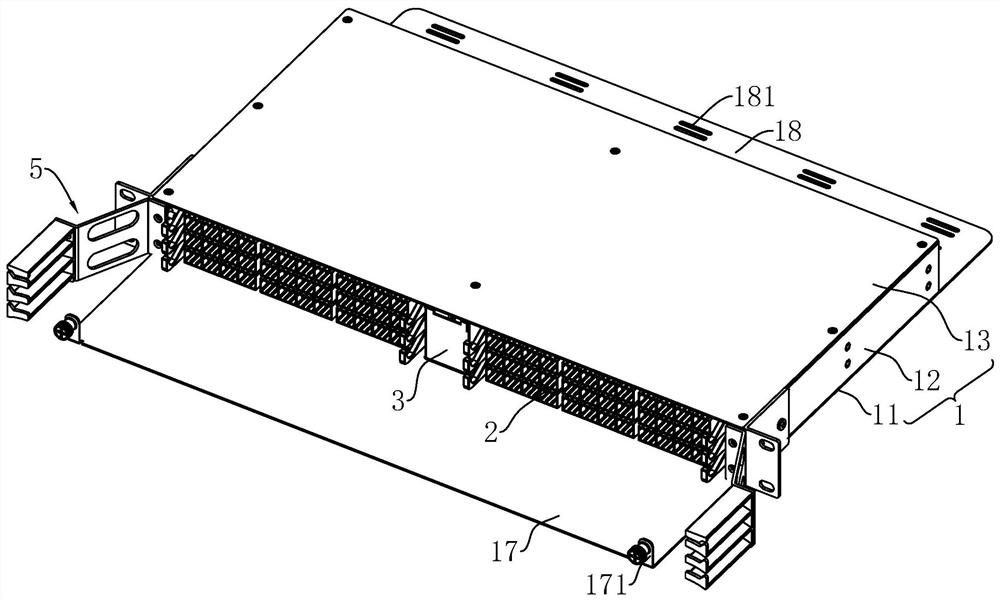
[0045] refer to figure 1 , a high-density optical fiber distribution frame, including a distribution box body 1 and a number of fiber-contained mold boxes 2 slidingly connected to the distribution box body 1, and the two ends of the distribution box body 1 are provided with openings.

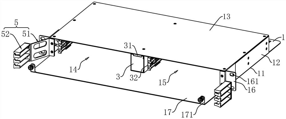
[0046] refer to figure 2 The distribution box body 1 includes a bottom plate 11, a pair of side plates 12 fixedly connected to the upper end surfaces on both sides of the bottom plate 11 and a top plate 13 fixedly connected to the upper end surfaces of the side plates 12, the bottom plate 11, the side plates 12 and the top plate 13 surround into the installation cavity. The distribution box body 1 is provided with a spacer 3 that divides the installation cavity into a first installation cavity 14 and a second installation cavity 15, the spacer 3 is parallel to the side plate 12, and the lower end surface of the spacer 3 is fixedly connected to the inner wall of the bottom plate 11 , the upper...

Embodiment 2

[0057] refer to Figure 8 , Figure 9 The difference between this embodiment and Embodiment 1 is that the second connecting plate 512 includes a fixed plate 5121 and a sliding plate 5122, the fixed plate 5121 is hinged to the first connecting plate 511 through the first hinge shaft 514, and the sliding plate 5122 Slidingly connected to the fixed plate 5121 , the end of the sliding plate 5122 away from the fixed plate 5121 is hinged to one side of the third connecting plate 513 through a hinge shaft. The fixed plate 5121 is provided with a sliding cavity for the sliding connection of the sliding plate 5122, the axial directions of the first hinge shaft 514 and the second hinge shaft 515 are vertically arranged, and the outer wall of the fixed plate 5121 is threaded with a butt joint. The sliding plate 5122 has a limit screw 53 that fixes the sliding position of the sliding plate 5122 .

[0058] refer to Figure 9 , Figure 10 The two sides of the second dust-proof plate 42 ...


PUM


Abstract

The invention relates to a high-density optical fiber distribution frame which comprises a distribution box body and a plurality of fiber containing mold boxes connected to the distribution box body in a sliding mode, the two ends of the distribution box body are open, and one end of each fiber containing mold box is provided with a plurality of first wiring ports used for being connected with optical fibers in a matched mode. A plurality of second wiring ports are formed in the other end of the fiber containing mold box, the distribution box body is provided with a wire arrangement frame, and the wire arrangement frame comprises a connecting frame arranged on the end wall of the distribution box body and a guide frame fixedly connected to the connecting frame. The guide frame comprises a guide plate fixed to the connecting frame and a plurality of supporting plates fixedly connected to the guide plate, and a wire arranging groove allowing optical fiber wire harnesses on the same fiber containing mold box to penetrate through is formed between every two adjacent supporting plates. The high-density optical fiber distribution frame has the effect of improving the uniformity of wiring.

Description

technical field [0001] The present application relates to the technical field of communication equipment, in particular to a high-density optical fiber distribution frame. Background technique [0002] Optical fiber communication is a communication method that uses light waves as a carrier and optical fiber as a transmission medium to transmit information from one place to another. It is called "wired" optical communication. Nowadays, optical fiber has become the main transmission mode in the world communication because of its wide transmission frequency bandwidth, high anti-interference and low signal attenuation, which is far superior to the transmission of cable and microwave communication. [0003] The optical fiber distribution frame (ODF) is used for the termination and distribution of the backbone optical cables in the optical fiber communication system, and can easily realize the link, distribution and scheduling of optical fiber lines. The function of the optical f...

Claims


Application Information

Patent Timeline
Patent Type & Authority Applications(China)
IPC IPC(8): G02B6/44
CPCG02B6/4452
Inventor 马奎李宝荣余振龙
Owner SHENZHEN ADTEK TECH CO LTD
Why Eureka
Try Eureka