
Accelerometer and methods thereof

Inactive Publication Date: 2005-02-15
NTH TECH
View PDF22 Cites 80 Cited by
  • Summary
  • Abstract
  • Description
  • Claims
  • Application Information

AI Technical Summary

Benefits of technology

The present invention provides an accelerometer which is much more sensitive than prior accelerometers. For example, with the present invention an accelerometer with a member with a typical charge density of 5×10¹² charges/cm2 and an electrode spacing of 1 μm, an average displacement of 0.01 angstrom yields an output potential of 1 mV. Since the sensitivity of the present invention is high, the accelerometer also can

Problems solved by technology

Although these prior accleremeters work, they have some limitations.
For example, typically these prior accelerometers have been complex MEMS devices with large numbers of interdigitated “comb” fingers that are needed to create a capacitor difference large enough to be interpreted.
As a result, these prior devices are large and expensive to manufacture.

Method used


Image

  • Accelerometer and methods thereof
  • Accelerometer and methods thereof
  • Accelerometer and methods thereof

Examples


Embodiment Construction

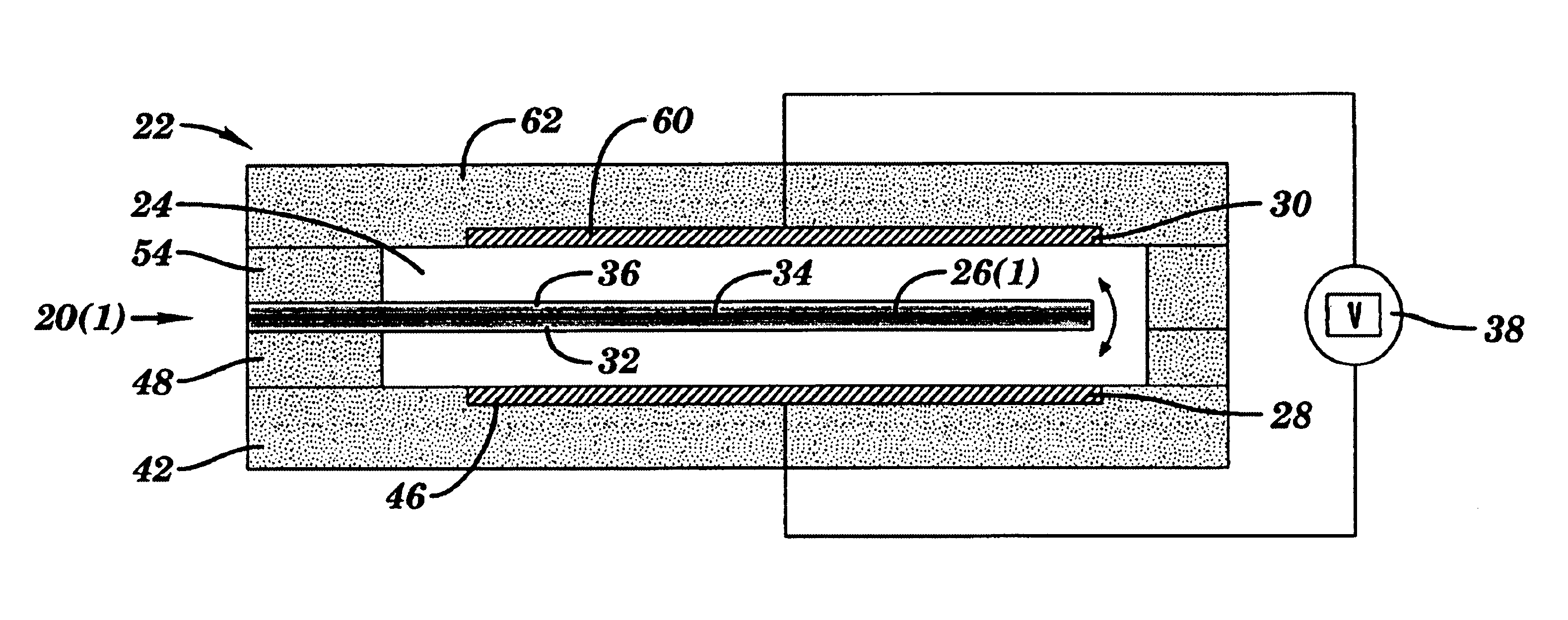
An accelerometer 20(1) in accordance with one embodiment of the present invention is illustrated in FIG. 8. The accelerometer 20(1) includes a housing 22 with a chamber 24, a member 26(1) with a stored static charge, and a pair of electrodes 28 and 30. The present invention provides an accelerometer 20(1) which is more sensitive and more compact than prior accelerometers.

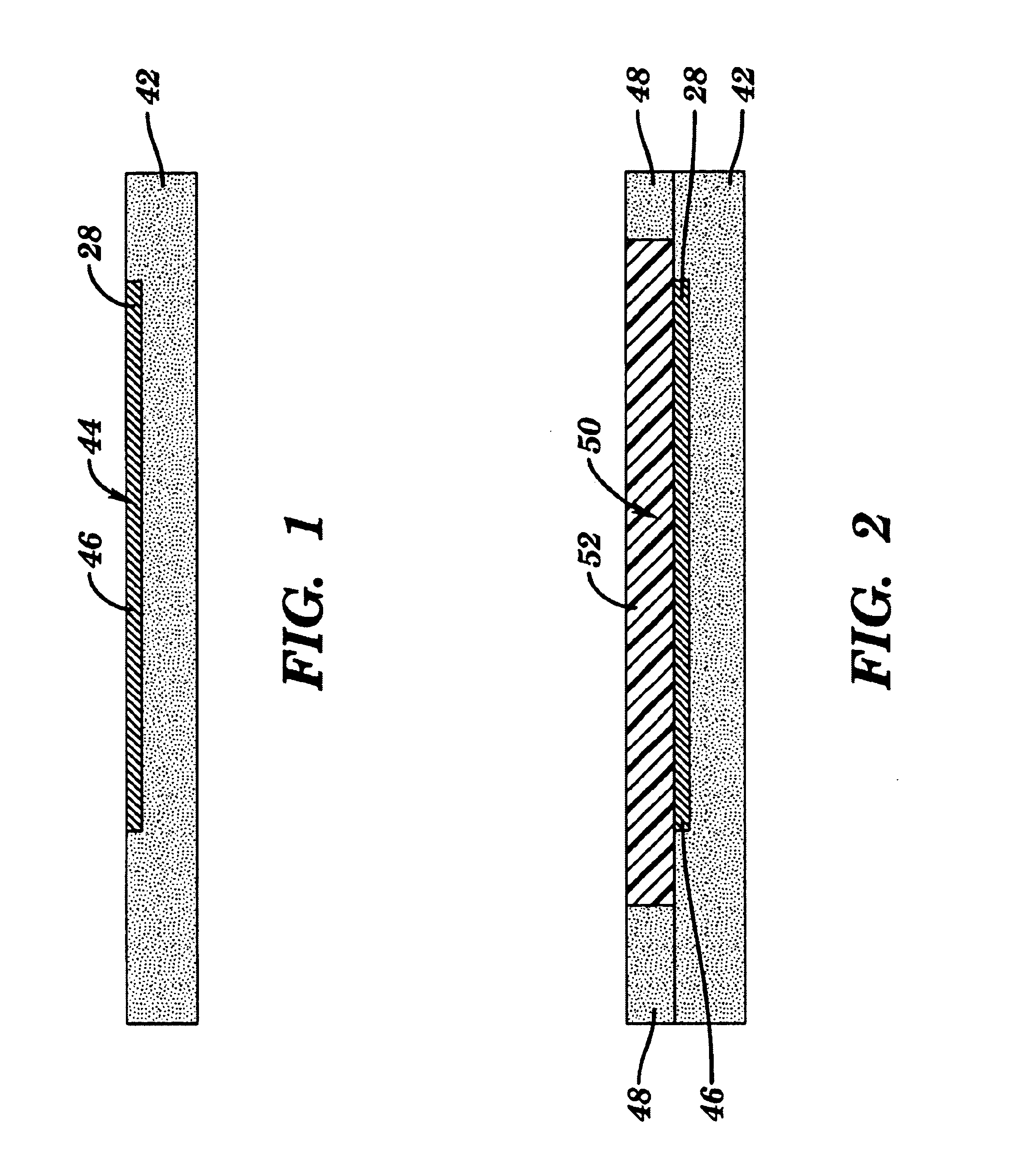
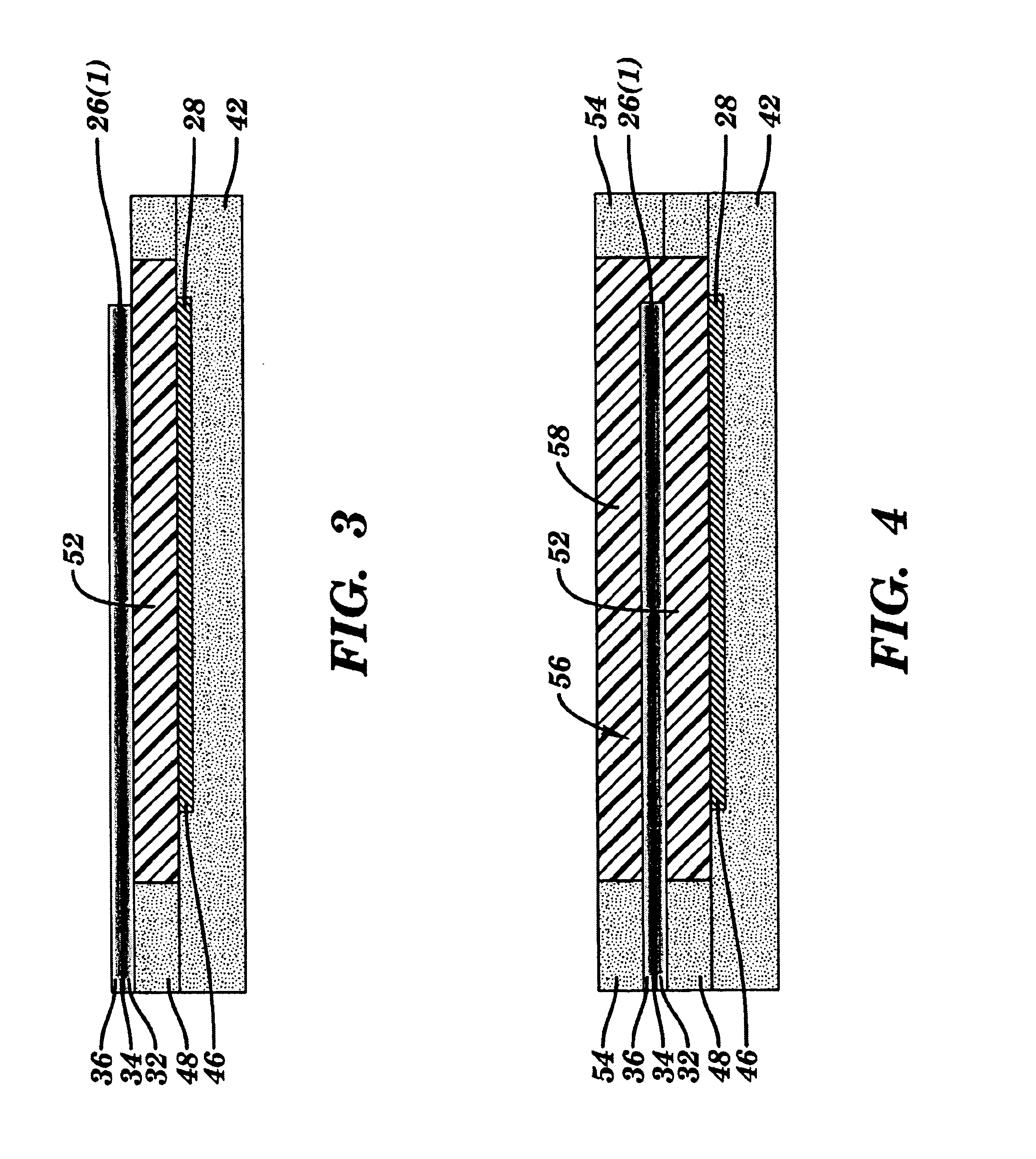
Referring to FIGS. 7 and 8, the housing 22 has an internal chamber 24 and is made of a variety of layers, although other types of supporting structures in other configurations and other numbers of layers, such as one or more, made of other materials can be used. The size of the housing 22 and of the chamber 24 can vary as required by the particular application.

The member 26(1) is connected to the housing along one edge and extends across the chamber 24 and is spaced from an inner wall of the housing 22, although other arrangements can be used, such as having the all of the edges of the member 26(1) secured to housin...


PUM


Abstract

An accelerometer includes a housing with a chamber, a member with a stored static charge, and a pair of electrodes connected to the housing. The member is connected to the housing and extends at least partially across the chamber. The pair of electrodes are each spaced from and on substantially opposing sides of the member from each other and are at least partially in alignment with each other. The member is movable with respect to the pair of electrodes or one of the pair of electrodes is movable with respect to the member.

Description

FIELD OF THE INVENTIONThis invention generally relates to accelerometers and, more particularly, relates to a high sensitivity accelerometer and methods thereof.BACKGROUND OF THE INVENTIONTypically, conventional accelerometers have a mass attached to a resilient, movable member and a stationary member. The stationary member together with the movable member form two plates of a capacitor. As the spacial position of the movable member is changed at non-constant rates, the mass moves toward or away from a stationary member. The change in the separation of the stationary and movable members results in a change in capacitance which can be correlated to a change in acceleration.Although these prior accleremeters work, they have some limitations. For example, typically these prior accelerometers have been complex MEMS devices with large numbers of interdigitated “comb” fingers that are needed to create a capacitor difference large enough to be interpreted. As a result, these prior devices ...

Claims


Application Information

Patent Timeline
IPC IPC(8): G01P15/125
CPCG01P15/125G01P2015/0828
Inventor POTTER, MICHAEL D.
Owner NTH TECH
Learn More