Negative inspiratory force manometer apparatus
- Summary
- Abstract
- Description
- Claims
- Application Information
AI Technical Summary
Benefits of technology
Problems solved by technology
Method used
Image
Examples
Embodiment Construction
Throughout the following detailed description, the same reference numerals refer to the same elements in all figures.
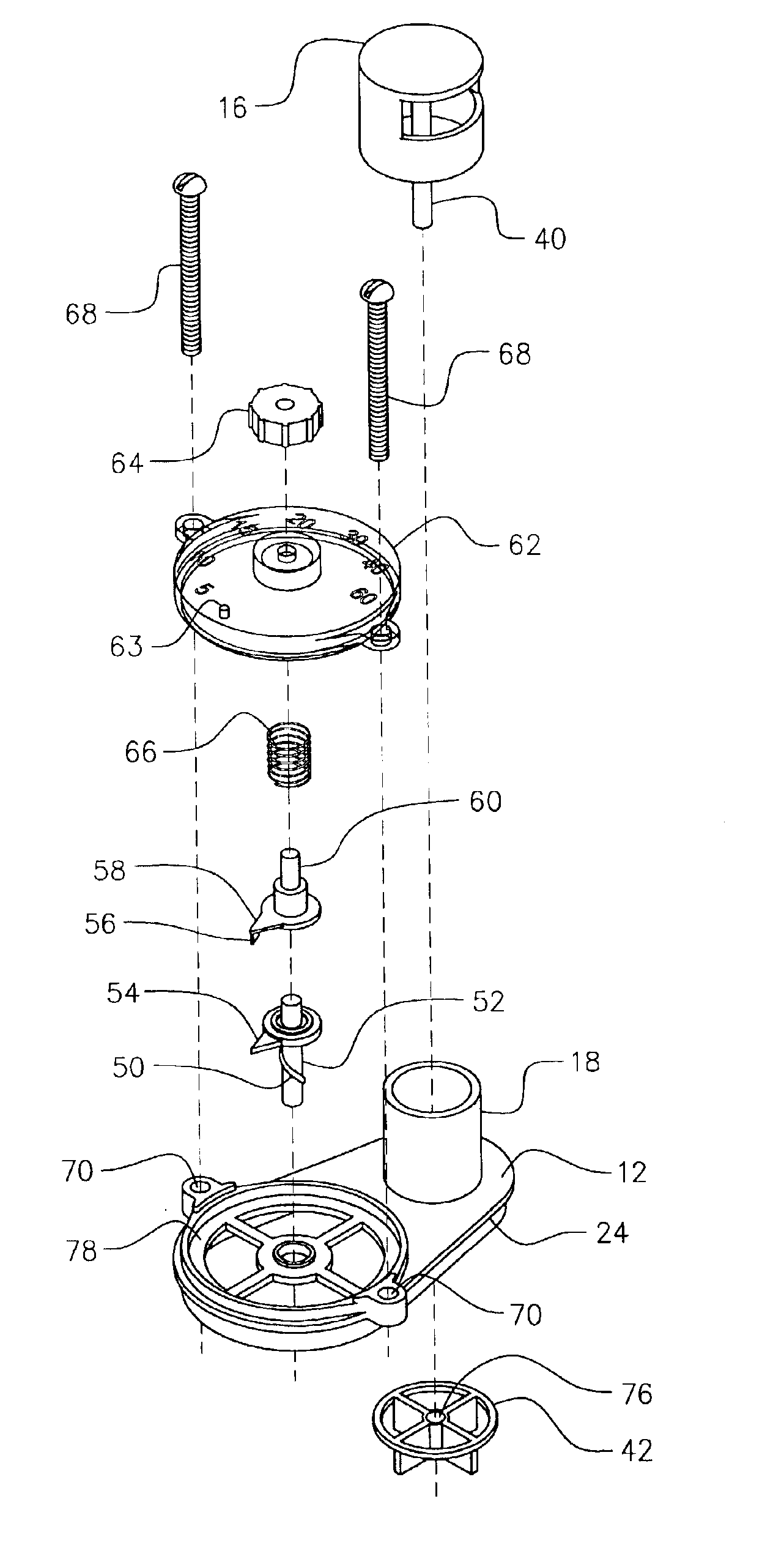
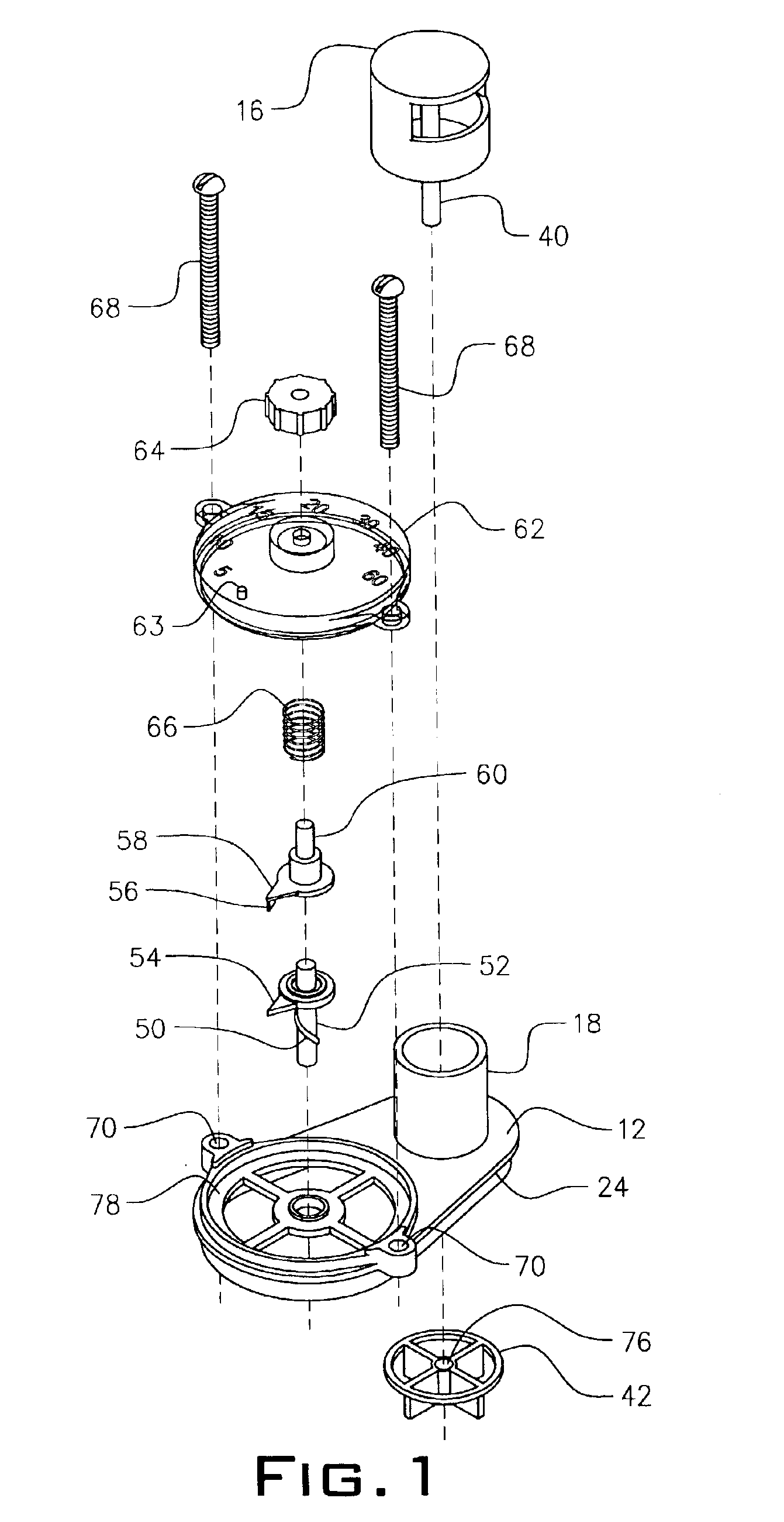
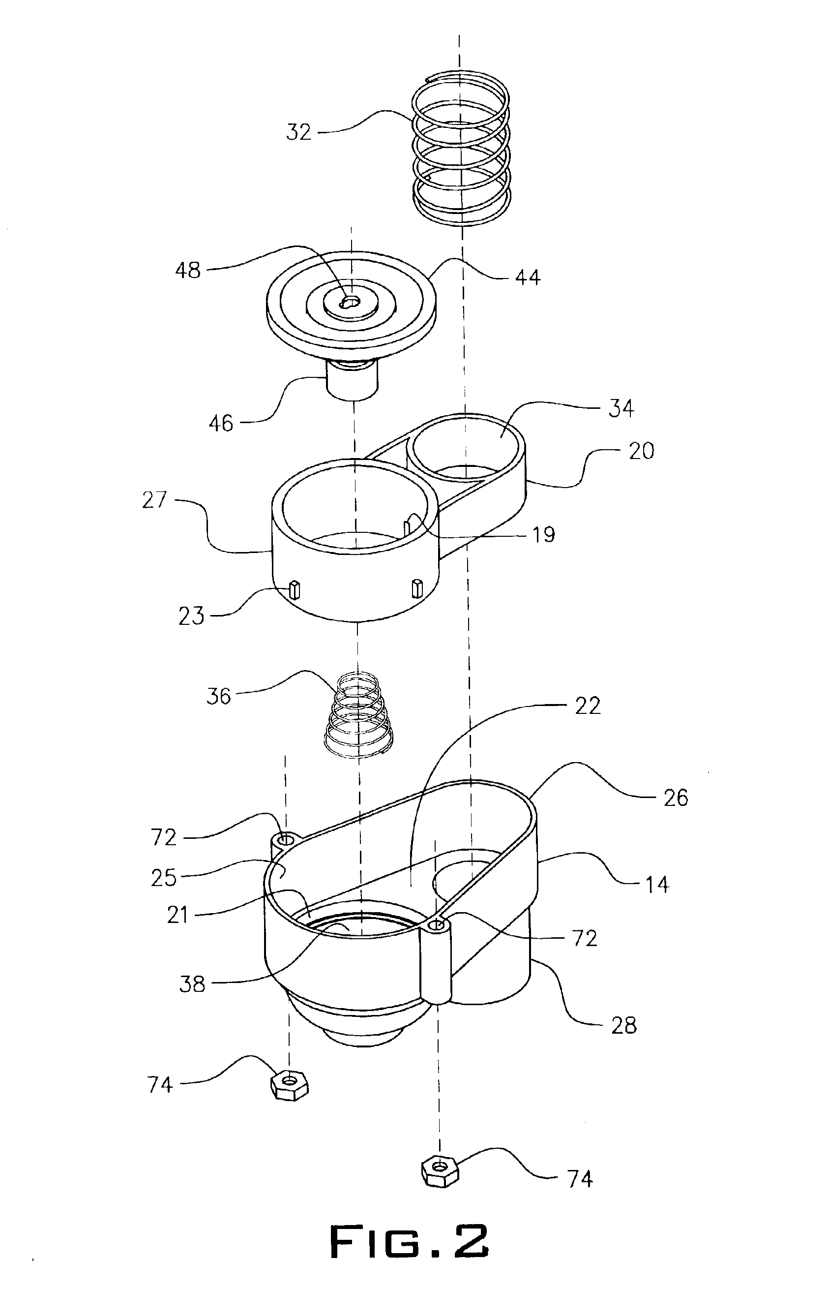
The unitary negative inspiratory force manometer apparatus shown in FIG. 3 has a top housing 12 and a bottom housing 14. A plunger cap 16 sits over an entrance port 18 on top housing 12. An intermediate housing 20 shown in FIG. 2 rests on an interior shelf 22 of bottom housing 14. Spacer tabs 23 projecting from an outside wall 27 of the intermediate housing 20 offsets from wall 25 over an annular portion 21 of interior shelf 22 as shown in FIGS. 2 and 4. A restricted orifice 19 in wall 27 allows flow of air to patient port 28. A flange 24 around top housing 12 rests on a top edge 26 of the bottom housing 14.
The patient port 28 is attached to an endotrachael tube 30. The patient's expired or inspired air passes through entrance port 18 and through channel 29 via patient port 28 when the plunger cap 16 is not depressed.
A plunger coil spring 32 is supported on shelf 22 a...
PUM
 Abstract
Description
Claims
Application Information
 - R&D
- Intellectual Property
- Life Sciences
- Materials
- Tech Scout
- Unparalleled Data Quality
- Higher Quality Content
- 60% Fewer Hallucinations
Browse by: Latest US Patents, China's latest patents, Technical Efficacy Thesaurus, Application Domain, Technology Topic, Popular Technical Reports.
© 2025 PatSnap. All rights reserved.Legal|Privacy policy|Modern Slavery Act Transparency Statement|Sitemap|About US| Contact US: help@patsnap.com


