Method and device for controlling a drive unit

a technology of drive unit and control device, which is applied in the direction of electric control, fuel injection apparatus, charge feed system, etc., can solve the problems of limited components and unoptimized known solutions, and achieve the effect of improving the monitoring accuracy and improving availability

Inactive Publication Date: 2005-02-15
ROBERT BOSCH GMBH
View PDF13 Cites 91 Cited by
  • Summary
  • Abstract
  • Description
  • Claims
  • Application Information

AI Technical Summary

Benefits of technology

Especially advantageous is furthermore a consideration of additional torque requests in the cold start, for example, for switching in additional consumers or control functions. This leads to an improved availability while simultaneously improving the accuracy of the monitoring.

Problems solved by technology

With a defective computation of these components, these components are limited.
The described known solutions do not provide optimal results in all cases.

Method used


Image

  • Method and device for controlling a drive unit
  • Method and device for controlling a drive unit
  • Method and device for controlling a drive unit

Examples


Embodiment Construction

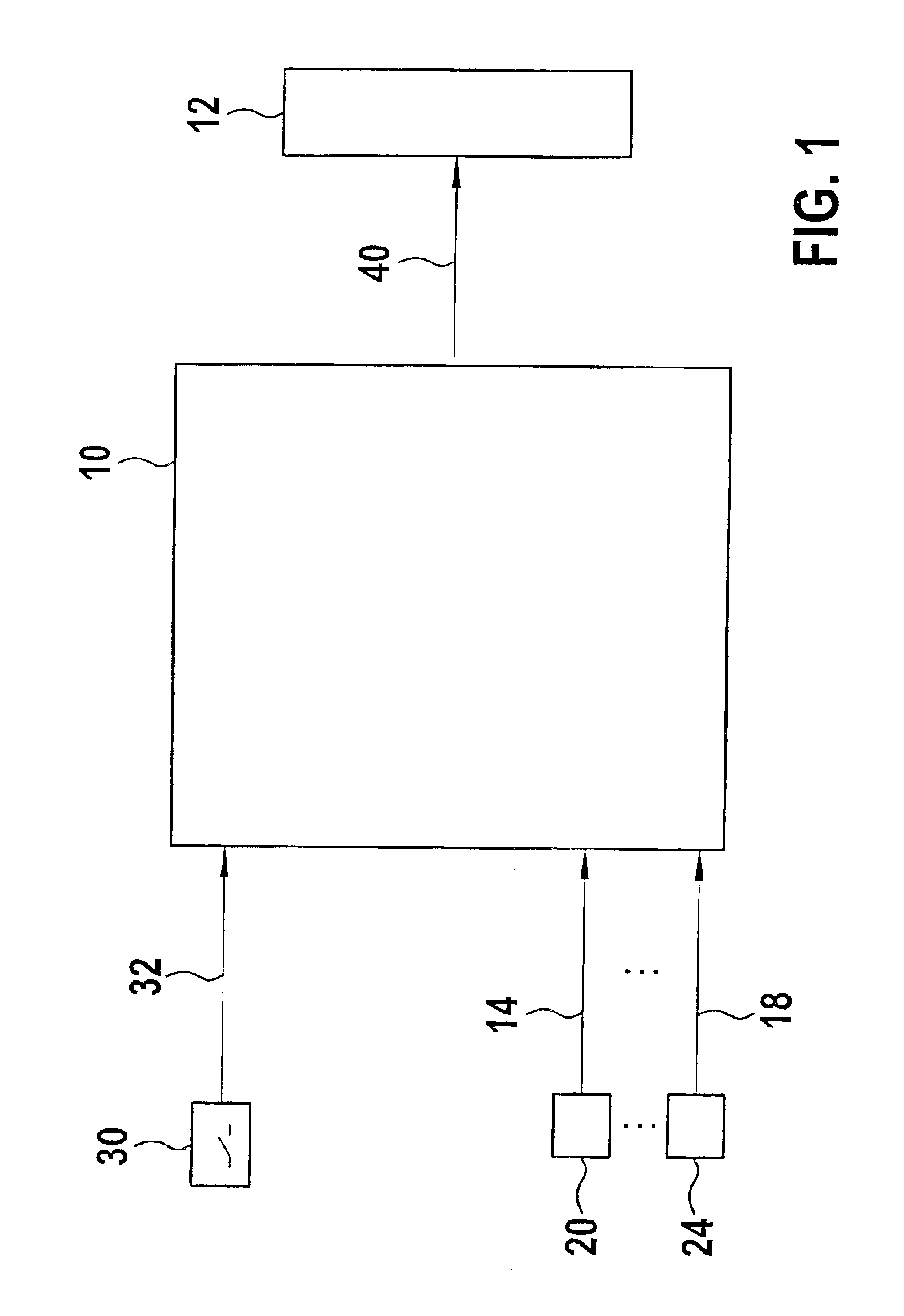
FIG. 1 shows a control unit 10 for controlling a drive unit 12. The control unit 10 includes at least a computer including a memory wherein the programs are stored which serve for controlling the drive unit 12. For executing these programs, operating variable signals of the drive unit and / or of the vehicle are inputted to the computer via input lines 14 to 18 from corresponding measuring devices 20 to 24. These operating variable signals are evaluated by the computer and are considered in the formation of the at least one actuating signal for the drive unit 12. Such operating variable signals are, for example, signals which represent the engine temperature, accelerator pedal position, et cetera.

The input quantities, which are supplied to the control unit 10, are converted into at least one actuating quantity by means of the programs running in the computer. This actuating quantity controls at least one condition variable of the drive unit 12 in the sense of the input variables via a...


PUM


Abstract

A method and an arrangement for controlling a drive unit are suggested wherein a maximum permissible value of an output quantity is determined. This maximum permissible value is compared to the actual value and, when the permissible value is exceeded by the actual value, reaction measures are initiated. The maximum permissible value is filtered at least in one operating state in accordance with filter means including a filter and a dead zone member. Furthermore, the maximum permissible value is continuously reduced in dependence upon the approaching of at least one quantity to a limit value. This quantity represents an operating state.

Description

FIELD OF THE INVENTIONThe invention relates to a method and an arrangement for controlling a drive unit.BACKGROUND OF THE INVENTION.A method and an arrangement of the above kind are disclosed in DE 195 36 038 A1 (U.S. Pat. No. 5,692,472). There, in the context of the control of a drive unit of a motor vehicle, for monitoring purposes, a quantity, which represents an output quantity of the drive unit, is compared to a maximum permissible value, which is pregiven for this quantity. Fault reaction measures are initiated when the quantity exceeds the pregiven permissible value. Examples of the output quantity of the drive unit are: the power of the drive unit or a torque of the drive unit, for example, the indicated torque, the output torque, et cetera. In one embodiment, the computer, which executes the control of the drive unit, includes at least two mutually separate program levels. The described comparison for monitoring purposes is computed in the second program level. The first pr...

Claims


Application Information

Patent Timeline
Patent Type & Authority Patents(United States)
IPC IPC(8): F02D41/08F02D41/02F02D45/00
CPCF02D41/021F02D41/08F02D2250/26F02D2250/18
Inventor PLAGGE, FRANKDUNKE, RALFBAUER, TORSTENBEDERNA, FRANKSTEINMANN, BERTHOLD
Owner ROBERT BOSCH GMBH
Why Eureka
Try Eureka