Apparatus and method for drilling with casing

a casing and apparatus technology, applied in the direction of drilling pipes, rotary drilling, borehole/well accessories, etc., can solve the problems of reducing the annular velocity of fluid, reducing the overall carrying capacity of fluid, and dropping drill cuttings out of fluid flow

Inactive Publication Date: 2005-02-15
WEATHERFORD TECH HLDG LLC
View PDF330 Cites 117 Cited by
  • Summary
  • Abstract
  • Description
  • Claims
  • Application Information

AI Technical Summary

Problems solved by technology

However, as the fluid travels the portion of the wellbore that was previously lined with casing, the enlarged cross-sectional area defined by the larger diameter casing results in a larger annular clearance between the drill string and the cased wellbore, thereby reducing the annular velocity of the fluid.
This reduction in annular velocity decreases the overall carrying capacity of the fluid, resulting in the drill cuttings dropping out of the fluid flow and settling somewhere in the wellbore.
This settling of the drill cuttings and debris can cause a number of difficulties to subsequent downhole operations.
For example, it is well known that the setting of tools against a casing wall is hampered by the presence of debris on the wall.
However, this method is not practical for downhole operations.
However, the higher annular velocity also increases the potential of wellbore erosion and increases the equivalent circulating density, which deals

Method used


Image

  • Apparatus and method for drilling with casing
  • Apparatus and method for drilling with casing
  • Apparatus and method for drilling with casing

Examples


Embodiment Construction

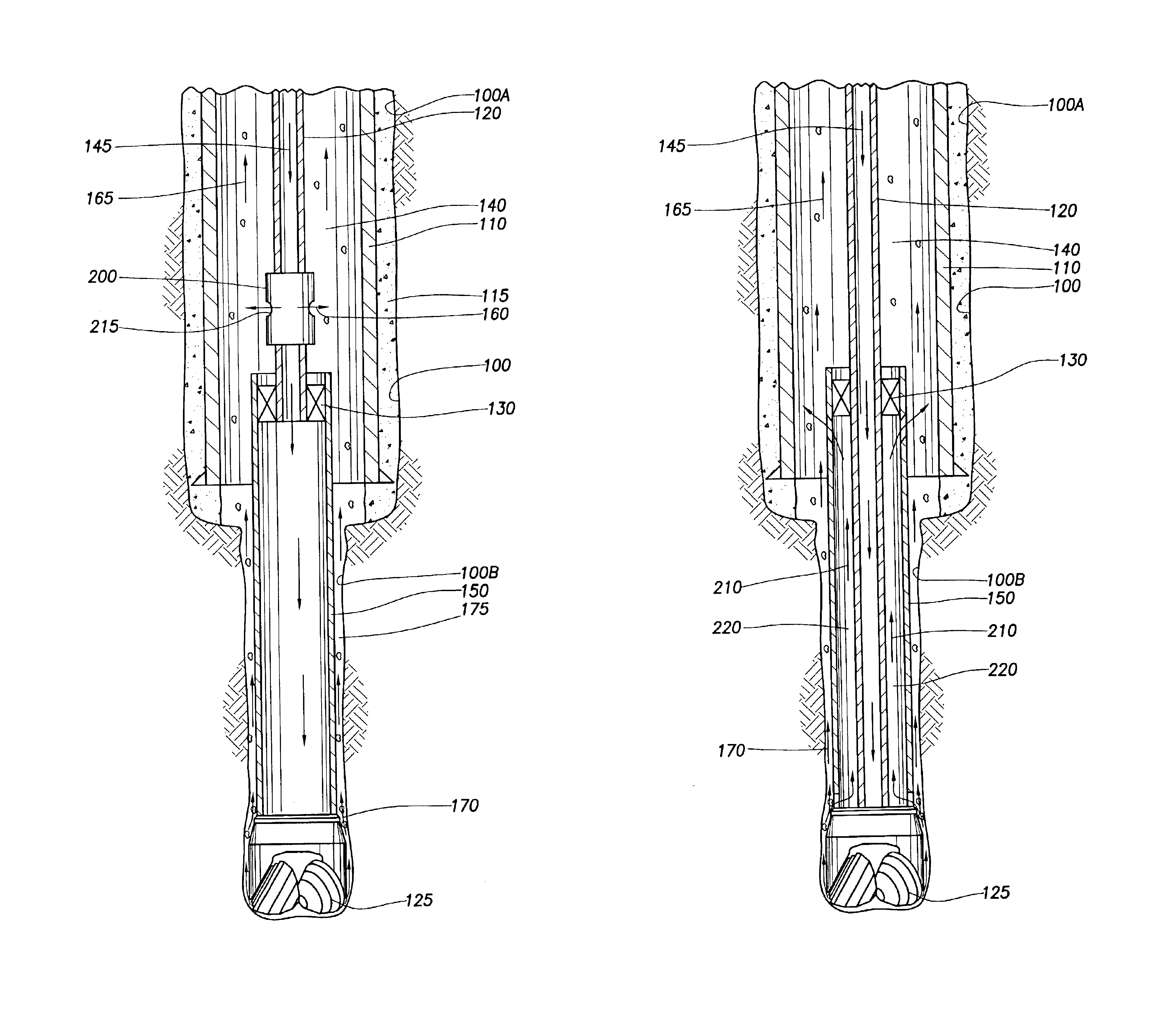
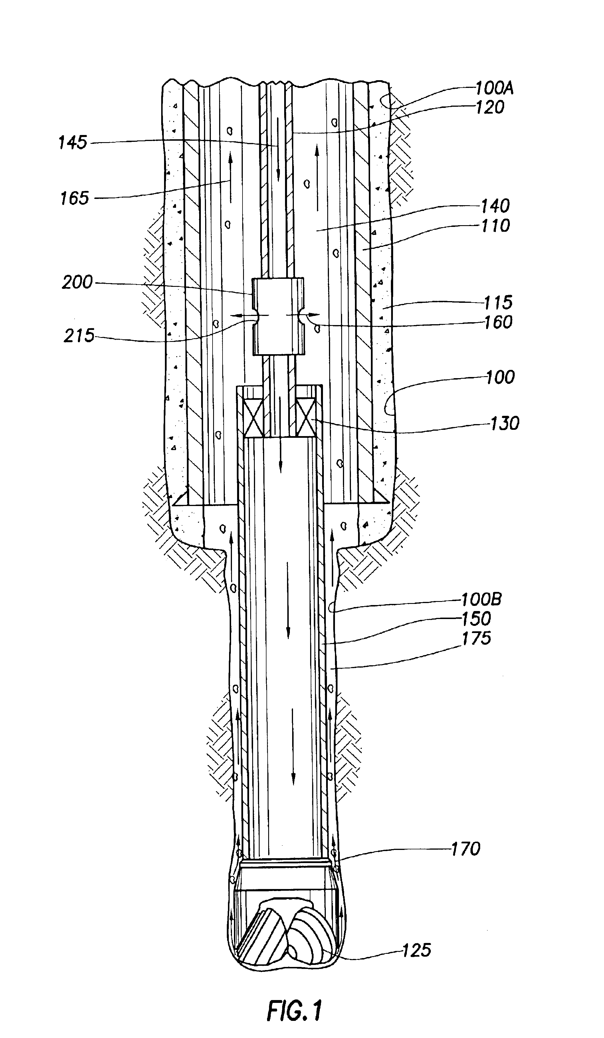
The present invention relates to apparatus and methods for effectively increasing the carrying capacity of the circulating fluid without damaging wellbore formations. The invention will be described in relation to a number of embodiments and is not limited to any one embodiment shown or described.

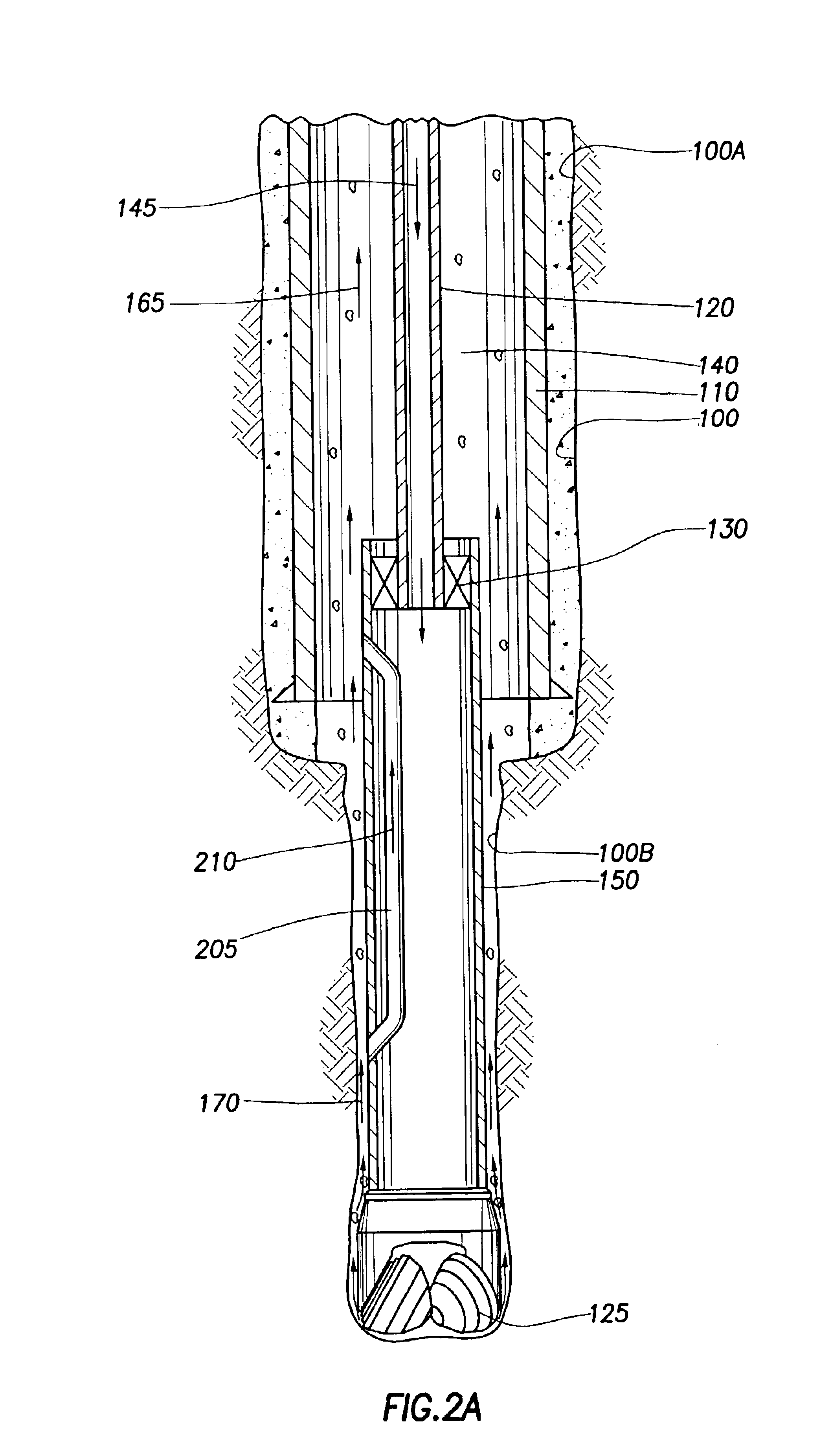
FIG. 1 is a section view of a wellbore 100. For clarity, the wellbore 100 is divided into an upper wellbore 100A and a lower wellbore 100B. The upper wellbore 100A is lined with casing 110 and an annular area between the casing 110 and the upper wellbore 100A is filled with cement 115 to strengthen and isolate the upper wellbore 100A from the surrounding earth. At a lower end of the upper wellbore 100A, the casing 110 terminates and the subsequent lower wellbore 100B is formed. Coaxially disposed in the wellbore 100 is a work string 120 made up of tubulars with a running tool 130 disposed at a lower end thereof. Generally, the running tool 130 is used in the placement or setting of downhole...


PUM


Abstract

The present invention generally relates to a method and an apparatus for drilling with casing. In one aspect, a method of drilling a wellbore with casing is provided, including placing a string of casing with a drill bit at the lower end thereof into a previously formed wellbore and urging the string of casing axially downward to form a new section of wellbore. The method further includes pumping fluid through the string of casing into an annulus formed between the casing string and the new section of wellbore. The method also includes diverting a portion of the fluid into an upper annulus in the previously formed wellbore. In another aspect, a method of drilling with casing to form a wellbore is provided. In yet another aspect, an apparatus for forming a wellbore is provided. In still another aspect, a method of casing a wellbore while drilling the wellbore is provided.

Description

BACKGROUND OF THE INVENTION1. Field of the InventionThe present invention relates to wellbore completion. More particularly, the invention relates to effectively increasing the carrying capacity of the circulating fluid without damaging wellbore formations. More particularly still, the invention relates to removing cuttings in a wellbore during a drilling operation.2. Description of the Related ArtIn the drilling of oil and gas wells, a wellbore is formed using a drill bit that is urged downwardly at a lower end of a drill string. After drilling a predetermined depth, the drill string and bit are removed, and the wellbore is lined with a string of casing with a specific diameter. An annular area is thus defined between the outside of the casing and the earth formation. This annular area is filled with cement to permanently set the casing in the wellbore and to facilitate the isolation of production zones and fluids at different depths within the wellbore.It is common to employ more ...

Claims


Application Information

Patent Timeline
IPC IPC(8): E21B21/00E21B21/10E21B7/20
CPCE21B21/103E21B7/20
Inventor GALLOWAY, GREGORY G.BRUNNERT, DAVID J.
Owner WEATHERFORD TECH HLDG LLC
Why Eureka
Try Eureka