Flow control valve that may be used for mold temperature control systems

a flow control valve and mold technology, applied in valve details, valve arrangements, thin material handling, etc., can solve the problems of high-capacity valves that may also be subject to the effects of water hammer, the control of the flow of pressurized high-temperature fluids, and the need for rugged valve construction, so as to reduce or eliminate the production of water hammer. , the effect of long service li

Inactive Publication Date: 2005-02-15
CITO PRODS
View PDF13 Cites 24 Cited by
  • Summary
  • Abstract
  • Description
  • Claims
  • Application Information

AI Technical Summary

Benefits of technology

In accordance with the present invention, a valve for control of coolant provides the capability of controlling the flow of cooling fluids over a wide temperature range and exhibits long service life while reducing or eliminating the production of water hammer. Furthermore, a distribution system including a plurality of valves in accordance with the present invention can be advantageously used in a plastics injection mold temperature control system which is capable of controlling heat transfer fluids to regulate the temperature of a plurality of channels in a mold. A controller can be used to operate such valves by using high and low pressurization states.
A cooling fluid distribution system in accordance with the present invention includes a manifold connecting a plurality of the valves. Such a system may have a selected number of such valves. Four valves may be advantageously used in a system such as in an injection mold temperature control system. Preferably, a pair of valves may be operated in coordination such that one of the two valves controls the supply fluid flow to a mold and the second valve controls the return fluid flow from the mold. Furthermore, a plurality of valve pairs may be operated in coordination such that each pair of valves controls fluid flow to a different channel in the mold. Such a plurality of valves in a fluid distribution system simplifies routing and connection of valves to both the air pressure lines and the hydraulic supply and return lines.

Problems solved by technology

Controlling the flow of pressurized high-temperature fluids such as, for example, water, demands rugged valve construction.
This is particularly true where long valve service life is required.
Such high-capacity valves may also be subject to the effects of water hammer when they close rapidly.
The operation of valves controlling the flow of pressurized heat transfer fluids will often lead to water hammer effects.
This can stress and damage hoses, pipes, joints, pumps and seals throughout the fluid system.
Since the fluid is often pressurized within the system, leaks can result and lead to damage to equipment, controls, materials, and people in the area, in addition to causing costly down-time.
However, these suppression devices, in addition to increasing cost, size, and weight, often introduce additional seals that must be maintained.
Other mitigation techniques include increasing the pipe diameter to reduce the fluid flow velocity; however, such mitigation suppression techniques can add significant cost and require extra space.
Rapid valve closure can directly cause water hammer.
Within a typical valve controlling a pressurized fluid flow, the plunger naturally tends to snap shut.
As the plunger closes, fluid flow becomes restricted; but, before flow is entirely shut off, the velocity of the fluid around the plunger increases, causing a corresponding decrease in pressure that naturally leads to an accelerating closure force on the plunger.

Method used


Image

  • Flow control valve that may be used for mold temperature control systems
  • Flow control valve that may be used for mold temperature control systems
  • Flow control valve that may be used for mold temperature control systems

Examples


Embodiment Construction

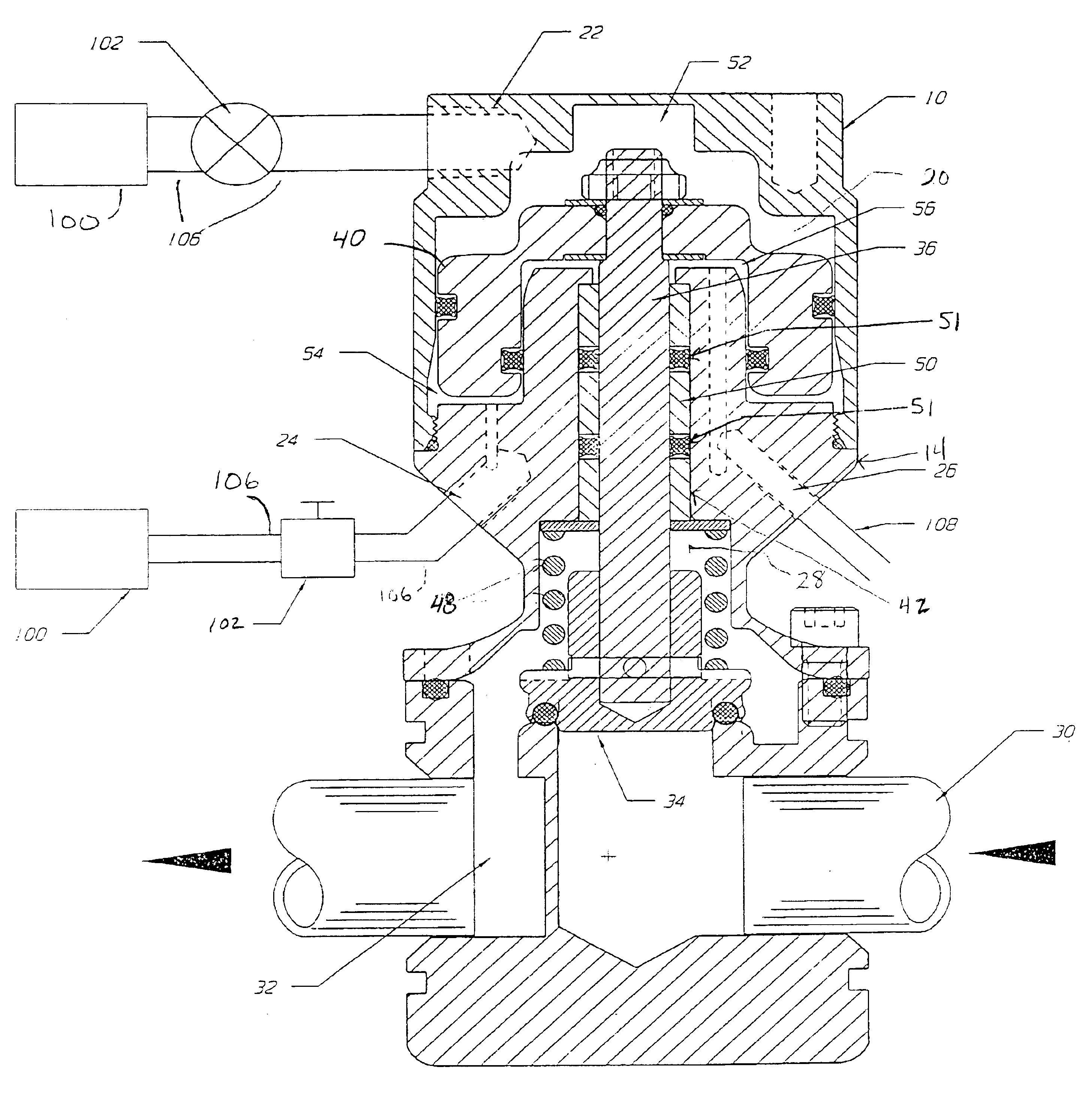
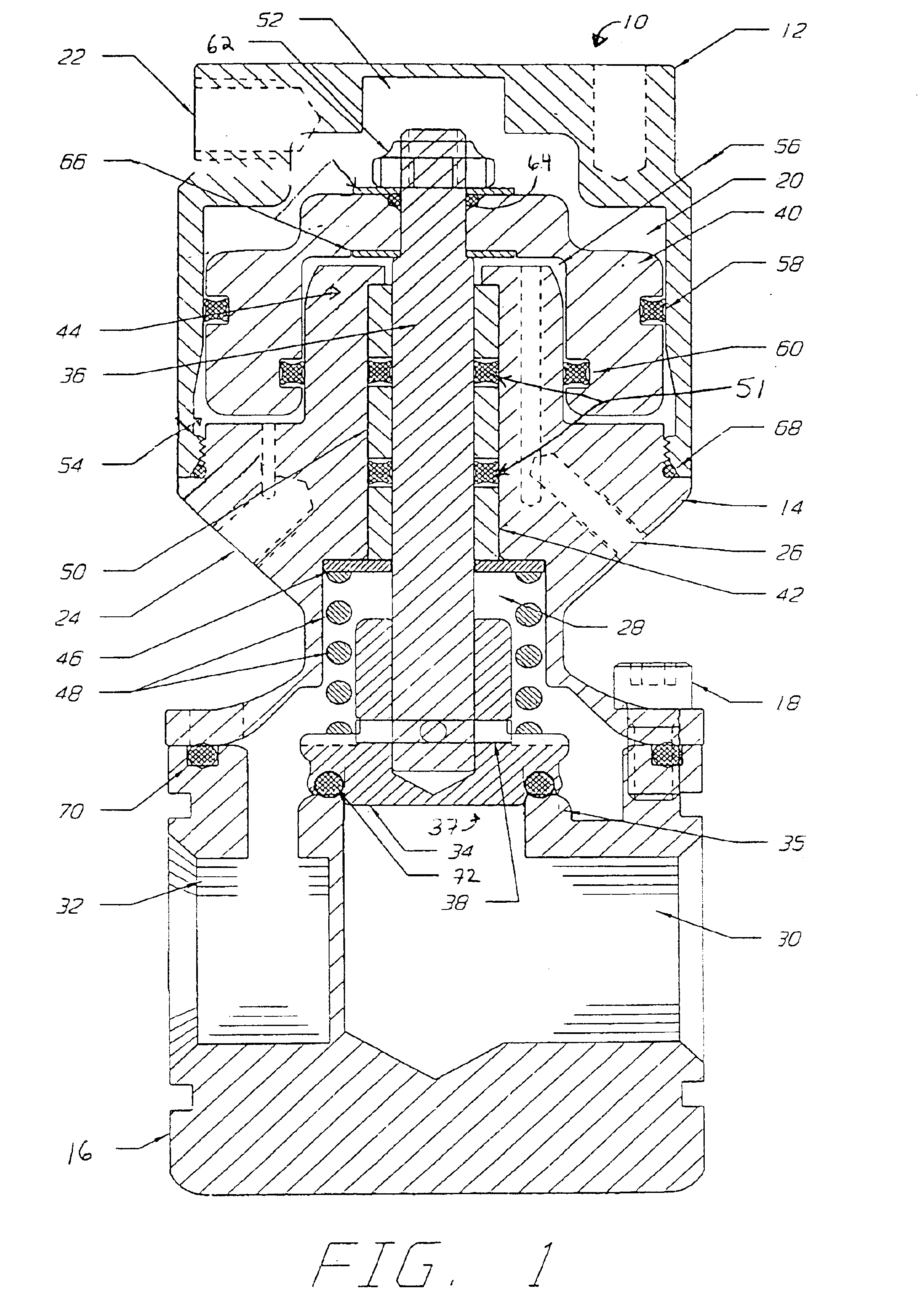
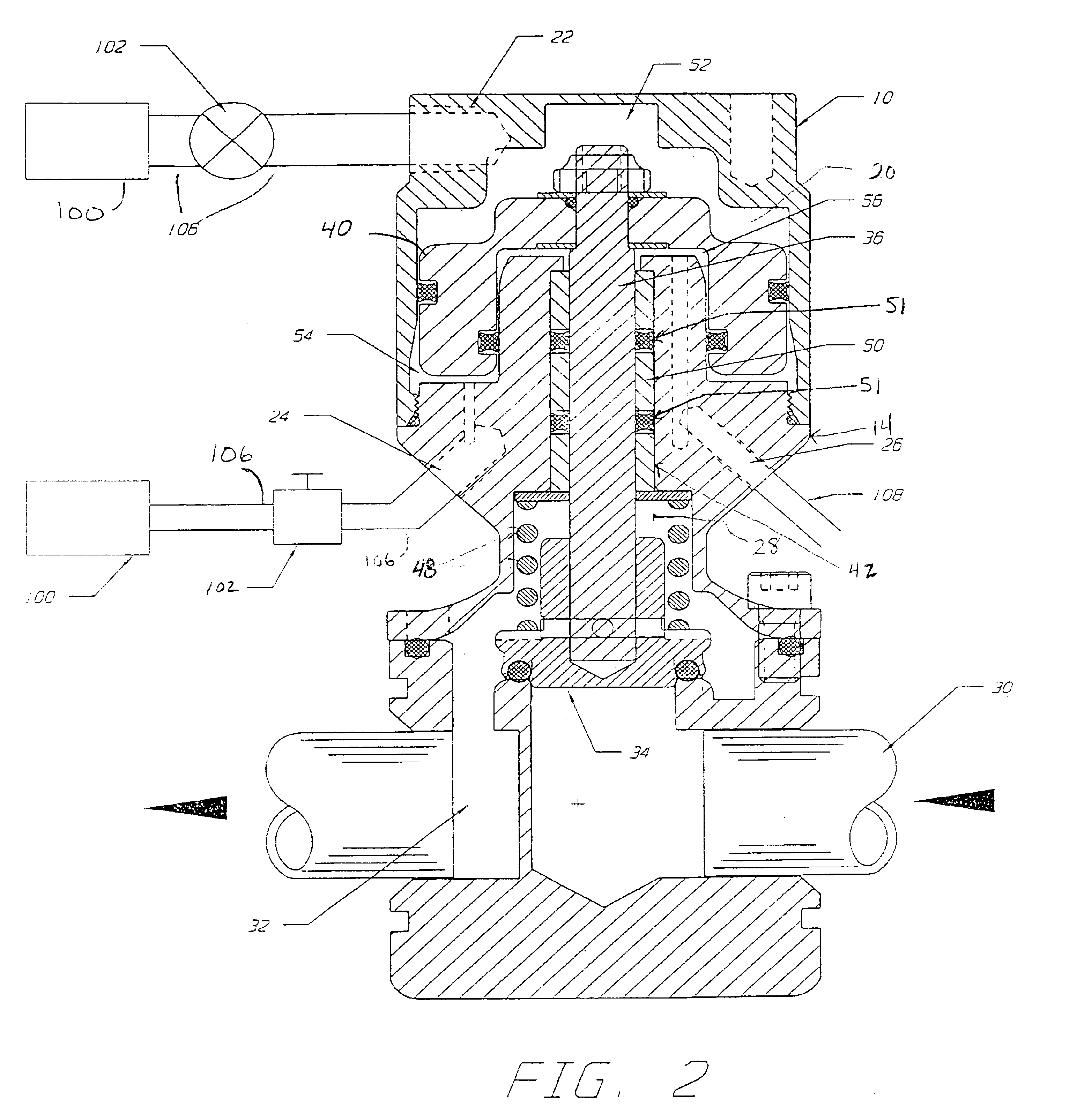
Referring to the drawings, a valve in accordance with the present invention is shown generally at 10 in cross-section in FIG. 1. The valve 10 includes a top housing 12 that is connected to a valve body housing 14. The valve body housing 14 is further connected to a valve mount 16, preferably attached using mounting hardware such as, for example, at least one mounting screw 18. The top housing 12 has internal surfaces defining a piston chamber 20. In fluid communication with the piston chamber 20 are an upper pressure port 22, a lower pressure port 24, and a vent port 26. The valve body housing 14 and the valve mount 16 have internal surfaces that together define a plunger chamber 28. The valve mount 16 has a hydraulic inlet port 30 and a hydraulic outlet port 32.

A valve plunger 34 is slideably disposed within the plunger chamber 28. When the valve plunger 34 is in the closed position engaged against a valve seat 35, pressurized fluid is blocked from flowing from the hydraulic inlet ...


PUM


Abstract

A valve is formed to resist snap-action closure forces and provides a smooth closing action to minimize or eliminate water hammer. The valve is opened and closed by modulating the relative air pressures above and below a piston in the valve. Because the air pressures above and below the piston produce partially offsetting forces on the piston, the net closure force on the valve plunger is limited, and the rate of valve closure is reduced enough to achieve the effect of minimizing water hammer. A separate vent port volume may vent to atmosphere to further limit valve closure speed, and to further reduce water hammer. The valve can provide the capability to control the flow of fluids over a wide temperature range over a long service life while reducing or eliminating water hammer. The valve is well suited for use in injection mold temperature control systems.

Description

FIELD OF THE INVENTIONThis invention relates generally to plastics injection mold temperature control systems and to valves capable of controlling the flow of coolant in an injection mold temperature control system.BACKGROUND OF THE INVENTIONThe flow of coolant (typically water) through the mold of plastics injection molding systems requires valves capable of rapidly controlling fluid flow over a wide temperature range. Injection molding is a well-known process which may be used for the fabrication of complexly-shaped plastic (or metal) parts. In the injection molding process, a molten plastic material is introduced into a mold and allowed to set or cure by cooling. Once the plastic is set or cured, the mold is opened, and the molded part is released. The temperature of the injection mold is preferably controlled so that the mold is at the proper temperature when the mold material is injected into the mold such that the object formed in the mold is set or cured at a rate that mainta...

Claims


Application Information

Patent Timeline
Patent Type & Authority Patents(United States)
IPC IPC(8): F16K31/16F16K31/122F16K31/163F16K47/00F16K47/02
CPCF16K47/023F16K31/122Y10T137/0318Y10T137/0396
Inventor WIEDER, HORST K.
Owner CITO PRODS
Why Eureka
Try Eureka