Internal combustion engine/generator with pressure boost

a technology of internal combustion engine and generator, which is applied in the direction of machines/engines, mechanical equipment, non-fuel substance addition to fuel, etc., can solve the problems of wasting substantial amount of heat energy, well-known unintended consequences of fossil fuel use, and ic engine used in a conventional car is still only about 20% efficient, etc., to reduce thermal pollution exhausted into the atmosphere, reduce fuel consumption, and increase usable electrical output power

Active Publication Date: 2016-12-29
RUSSELL ENERGY CORP
View PDF4 Cites 3 Cited by
  • Summary
  • Abstract
  • Description
  • Claims
  • Application Information

AI Technical Summary

Benefits of technology

[0047]An object of at least one embodiment of this invention is to provide a one-piece Engine / Generator configuration having all the added benefits provided by the combination of a Pressure Boost event or events so as to provide an even greater amount of usable electrical output power with reduced fuel consumption.
[0048]Another object of at least one embodiment of this invention is to provide a one-piece Engine / Generator configuration having all the added benefits provided by the combination of a Pressure Boost event or events so as to reduce thermal pollution exhausted into the atmosphere.
[0049]A further object of at least one embodiment of this invention is to provide an engine or Engine / Generator combination that is even smaller, lighter, more power dense and more thermally efficient than conventional engines or previous Engine / Generator designs.
[0050]It is still a further intention of at least one embodiment of the invention to provide a method of increasing the production of usable energy in an internal combustion, piston and cylinder engine, while reducing or eliminating the production of NOx gases.
[0051]Another object of at least one embodiment of this invention is to provide a one piece Engine / Generator configuration with a modified piston, having an extended apron used in concert with the independently controlled movement of the piston so as to control the timing and introduction of the cylinder purge / cooling / pre-compression air into the cylinder, in order to eliminate the need for additional internal or external valve means.

Problems solved by technology

There are also well-known unintended consequences related to the use of fossil fuels such as air pollution and global warming.
Yet after 139 years of constant development the IC engine used in a conventional car is still only about 20% efficient.
A substantial amount of heat energy is simply wasted.
Some typical problems of this type of engine include;1. The operating speed; as the specific function of all IC engines is to provide rotating, mechanical energy outside of the engine (by way of attachment to the crankshaft of the engine), and as most applications that require IC engines also require broad variations in the operating speed of the IC engine (for example; the typical engine used in automobile applications operates between 600 RPM and 6,000 RPM), and as both the low-speed operation and the high-speed operation of the IC engine provide greatly reduced levels of output power and fuel efficiency while producing increased levels of pollutants, the variations in the operating speed of an internal combustion engine are clearly undesirable.a. By contrast the engine of the present invention was specifically designed to operate at a relatively fixed speed allowing the design parameters to maximize combustion efficiency, output power and fuel efficiency, while reducing or eliminating the production of pollutants at all times during operation.2. The crankshaft; the use of a crankshaft in a conventional IC engine (especially in multi-cylinder applications) demands that all facets of the piston movement are identical.
Unfortunately, it is not desirable to have each of the cycles of operation configured in such a way that they are identical in every way.
The most obvious problem with this series of events is, if the spark is initiated at 12° before TDC (and even earlier during high-speed operation) this means that the combustion of the air / fuel mixture within the cylinder begins during the upward movement of the piston while still in the compression cycle.

Method used


Image

  • Internal combustion engine/generator with pressure boost
  • Internal combustion engine/generator with pressure boost
  • Internal combustion engine/generator with pressure boost

Examples


Embodiment Construction

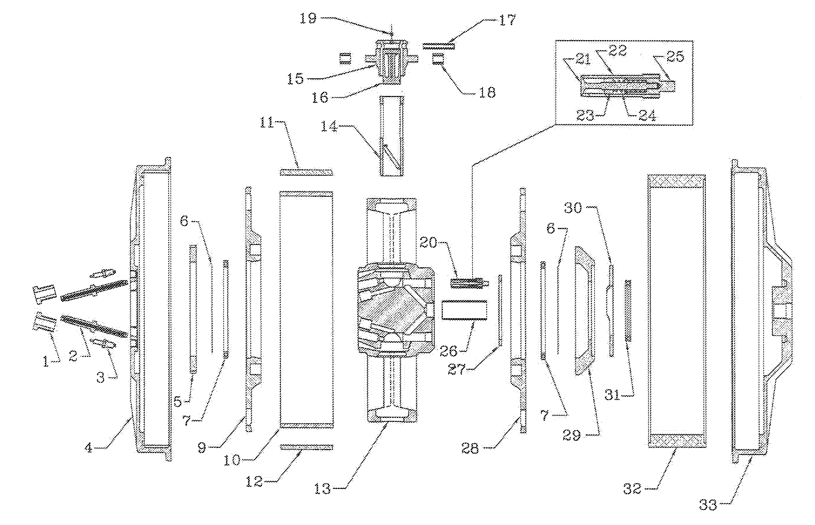
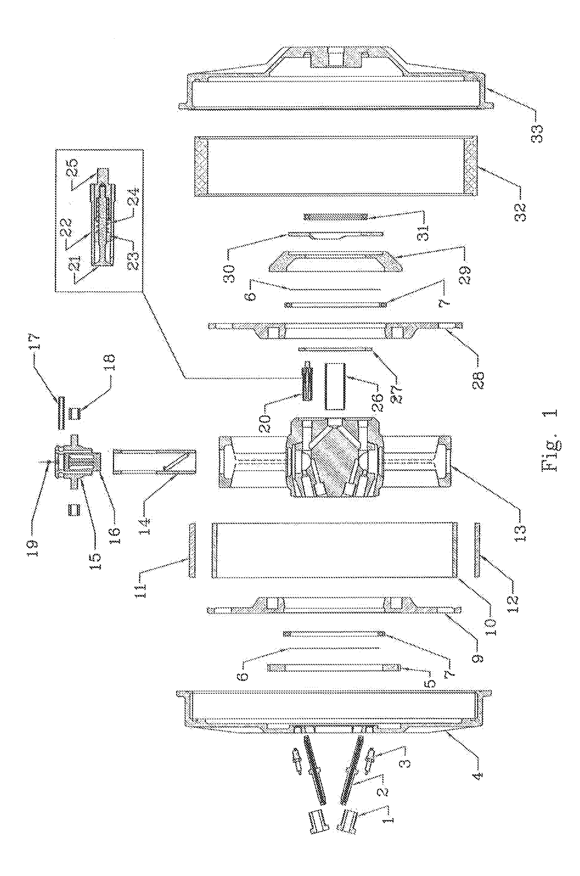
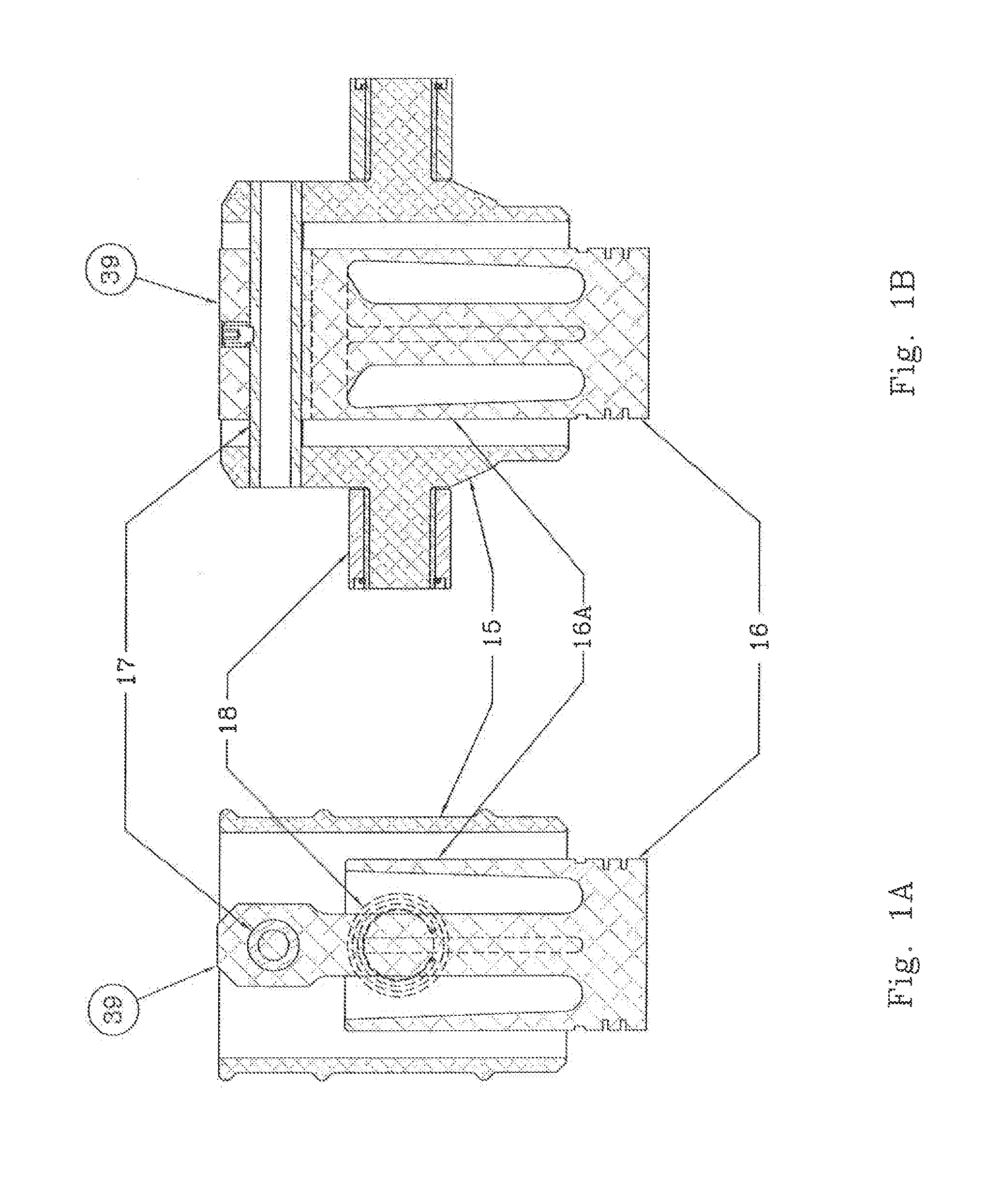
[0083]The description which follows will set forth the features of several preferred embodiments of this invention and more specifically will describe the features of an improved Engine / Generator similar to U.S. Pat. No. 8,113,165 B2 and a unique Pressure Boost system working together yet independently so as to further optimize the relatively fixed speed combustion process as well as the harvesting of the heat energy produced. The Engine / Generator having a modified rotating twin cam-track configuration, an altered piston with an extended piston apron, an altered and extended piston movement and a dual medium fuel / water injector system for the purpose of utilizing the unique Pressure Boost feature of the present invention so as to further optimize and improve the combustion and power take off processes, while increasing output power, reducing fuel consumption, reducing or eliminating the production of NOx gasses during the combustion process, reducing wasted heat energy while substan...


PUM


Abstract

This invention relates to improvements in internal combustion engines. More particularly it relates to increased levels of usable electrical energy production and fuel efficiency within a relatively fixed speed, cam-track style Engine/Generator when combined with the secondary injection or injections of a rapidly expanding medium (usually water) into the engines combustion chambers during and after the combustion process has been initiated. The injection of said medium causing reduced fuel consumption, increased cylinder pressure, an extended usable piston stroke length, and increased usable energy production, while reducing the temperature of the combustion gases in order to control or eliminate the production of the pollutant, NOx and to further reduce thermal pollution exhausted into the atmosphere.

Description

BACKGROUND OF THE INVENTION[0001]In these times with an ever increasing global population, there is an ever increasing demand for energy. Although energy produced by the consumption of fossil fuels is physically easy, personally convenient and relatively inexpensive now, change is in the air. We consume more fossil fuels now than ever before and the demand is constantly increasing while our reserves continue to be reduced. There are also well-known unintended consequences related to the use of fossil fuels such as air pollution and global warming. It is incumbent on us as stewards of our planet to use only what we need and save all that we can for future generations.[0002]Since the invention of the Otto cycle engine in 1876 there have been many improvements and advancements to the internal combustion (IC) engine design. Yet after 139 years of constant development the IC engine used in a conventional car is still only about 20% efficient. A substantial amount of heat energy is simply...

Claims


Application Information

Patent Timeline
Patent Type & Authority Applications(United States)
IPC IPC(8): F02M25/03F02B1/14F01N3/08F02B1/06
CPCF02M25/03F02B1/06F01N2570/14F01N3/0842F02B1/14F02B47/02F01B1/0624F02B2275/36Y02T10/12
Inventor RUSSELL, ROBERT L.
Owner RUSSELL ENERGY CORP
Why Eureka
Try Eureka