Carousel shelving unit

Inactive Publication Date: 2005-02-15
SMITH JOHN T
View PDF19 Cites 53 Cited by
  • Summary
  • Abstract
  • Description
  • Claims
  • Application Information

AI Technical Summary

Benefits of technology

In preferred embodiments, the cam-track segments include inner and outer track segments, and the tracking elements include inner and outer tracking elements that operatively engage the inner and outer track segments, respectively. The track segments are configured to effect pivoting of the tracking elements from a first position that is associated with the horizontal position of the shelves to a second position that is associated with the tipped position of the shelves and the back to the first position as the shelves move therethrough.
The invention contemplates providing the inner and outer track segments of the cam-track segments with respective cam surfaces that progress from parallel to non-parallel and back to parallel, and providing the inner and outer tracking elements in a normal skewed alignment associated with the horizontal position of the shelves such that the cam surfaces effect pivoting of the tracking elements away from and then back to their normal skewed position and the shelves from horizontal to tipped and back to horizontal as the shelves travel through the cam-track segments.
The invention alternately contemplates providing the inner and outer track segments of the cam-track segments with respective cam surfaces, one of which is lengthened as compared to the other, and providing the inner and outer tracking elements in a normal non-horizontal alignment position associated with the horizontal position of the shelves, to effect the pivoting and return of the tracking elements as the shelves as they travel through the cam-track segments.
In one embodiment, the inner and outer track segments are provided with respective cam surfaces that approach one another and then recede from one another, and the inner tracking elements are positioned above the outer tracking elements. In this instance, the cam surfaces are configured to cam the tracking elements towards horizontal, to effect tipping of the shelves, and to then return the tracking elements to their previous position to return the shelves to horizontal as they travel through the cam-track segments.
In an alternate embodiment, the inner and outer track segments are provided with respective cam surfaces that recede from one another and then approach one another, and the inner tracking elements are positioned below the outer tracking elements. In this instance, the cam surfaces are configured to cam the tracking elements towards vertical alignment, to effect tipping of the shelves, and to then return the tracking elements to their previous position to return the shelves to horizontal as they travel through the cam-track segments.
In accordance with other aspects of the invention, and in carrying out a preferred embodiment, the carousel shelving unit includes a set of shelves mounted for vertical carousel rotation in an upright cabinet. The cabinet is provided with structural frame elements and cover panels generally enclosing at least the front and sides of the cabinet. The closure panels are suitable for placement of product information and/or advertising. The cabinet is further provided with a front opening at a handicap accessible height for access

Problems solved by technology

However, such use of conventional shelves has certain drawbacks and disadvantages to both the store and the consumer.
For example, use of conventional shelves to display merchandise can result in inefficient use of floor space because it limits the useable height of shelving to that which the consumer can reach.
Use of conventional shelves also presents obstacles to consumers that cannot reach the top or bottom shelves; such as consumers in wheelchairs or mobile carts

Method used


Image

  • Carousel shelving unit
  • Carousel shelving unit
  • Carousel shelving unit

Examples


Embodiment Construction

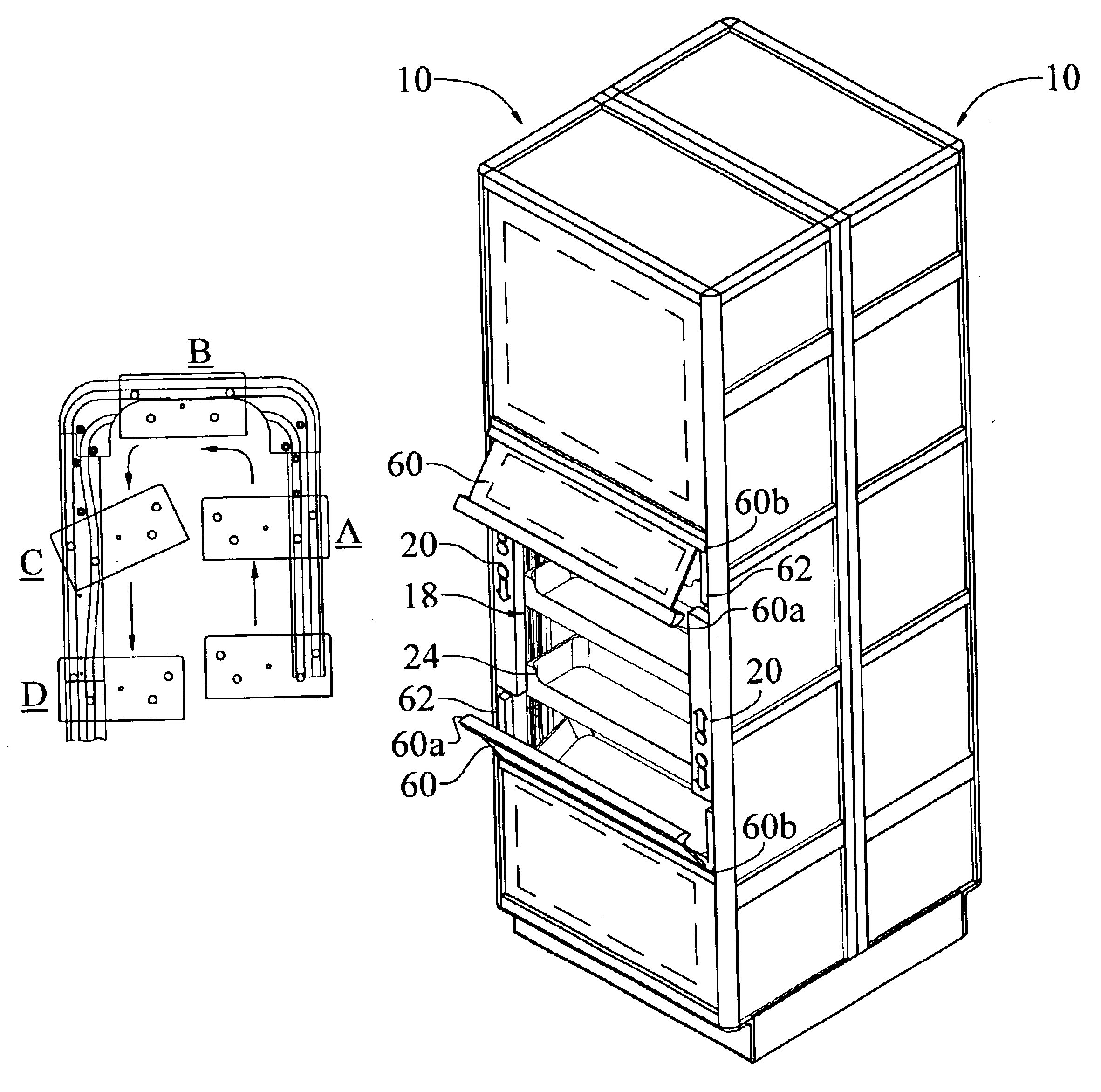
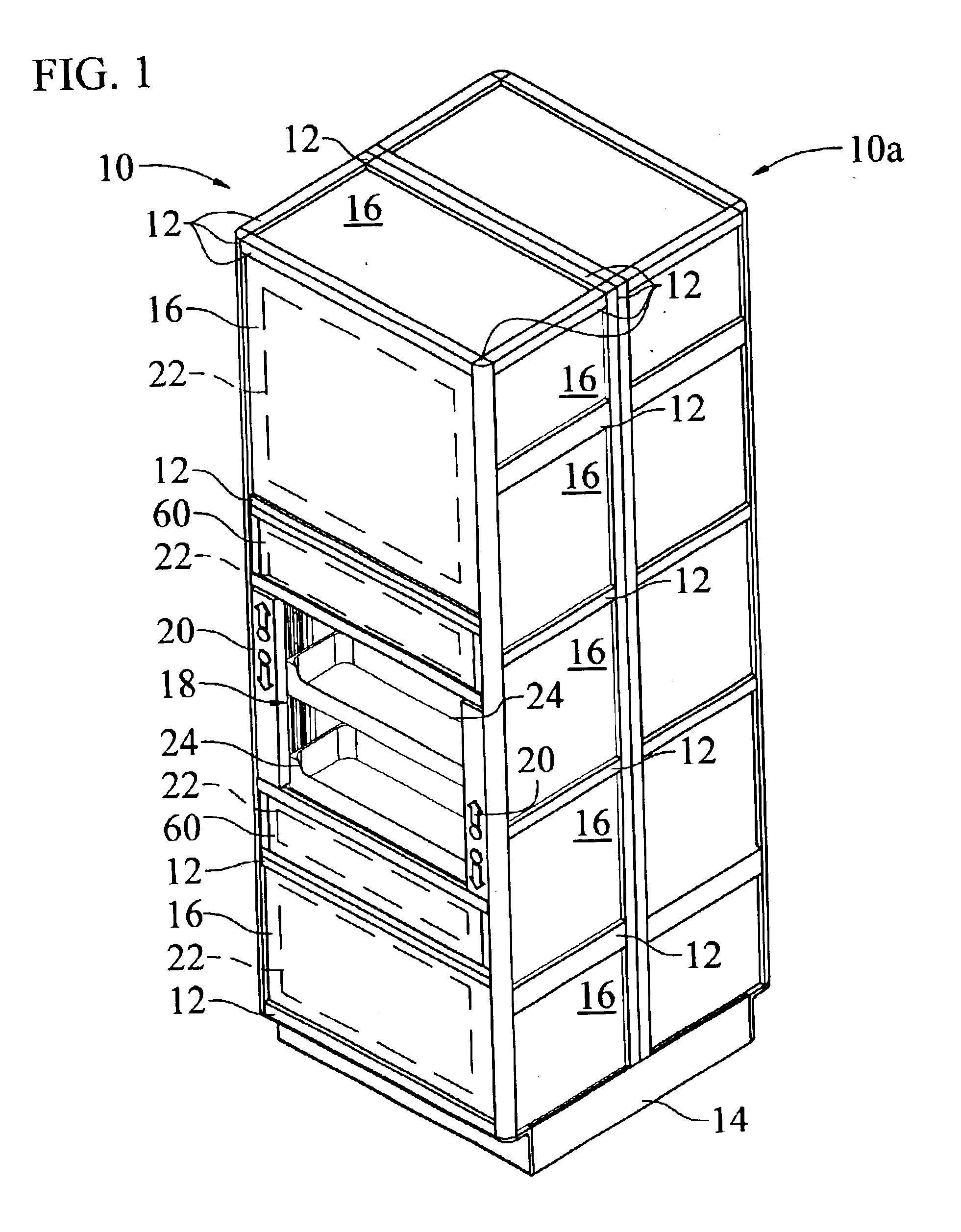
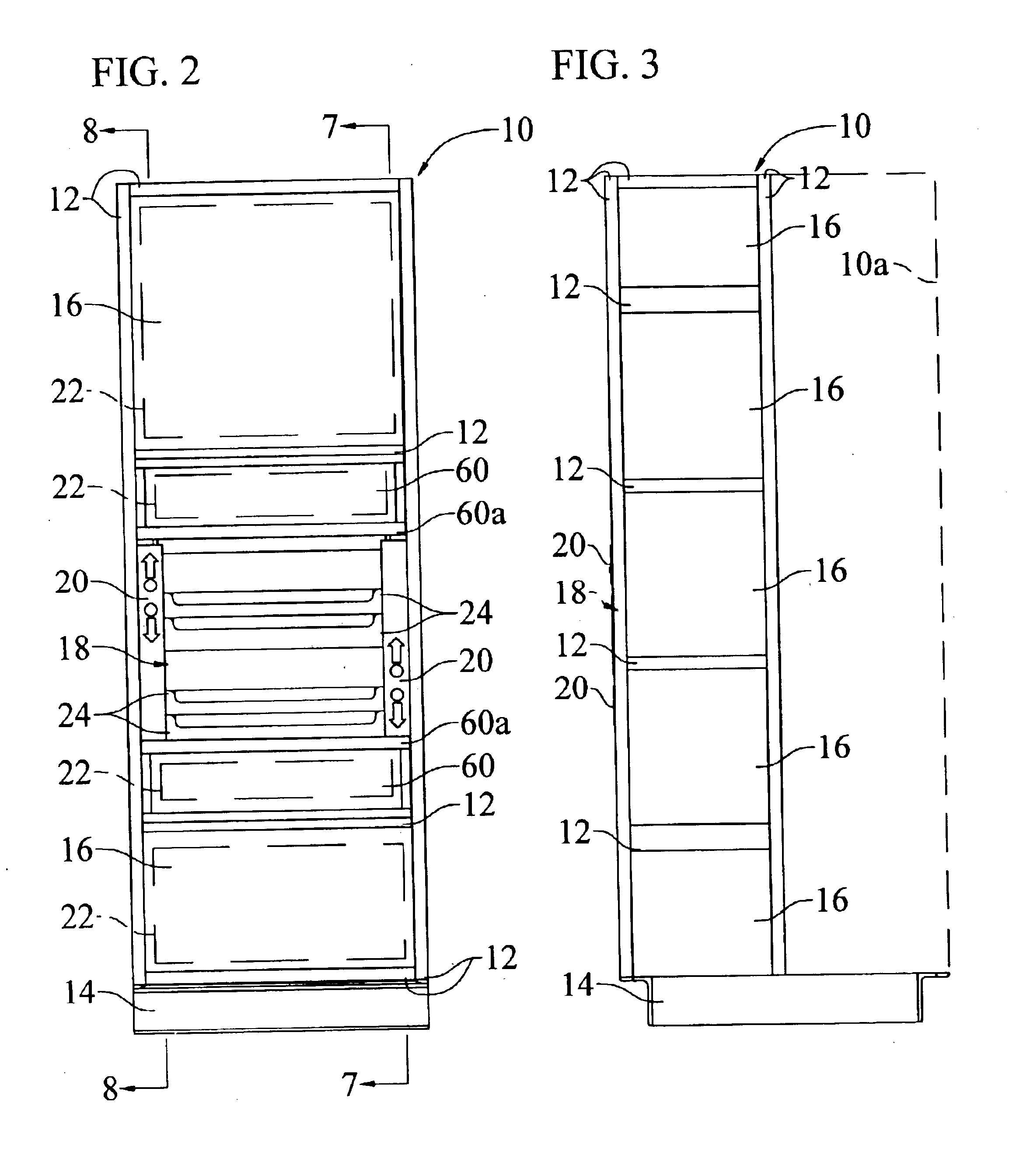
Referring now to FIGS. 1-3, there is shown a carousel shelving unit 10 in accordance with the invention.

Briefly, the shelving unit 10 includes an upright cabinet, and a set of shelves 24 mounted in the cabinet for vertical power-driven carousel rotation therein. The cabinet includes an upright frame structure established with frame elements 12 secured together, and closure panels 16 connected to the frame elements to generally enclose the carousel-mounted set of shelves. In the embodiment shown, a base 14 supports the cabinet in its vertical position from a floor or other foundation. In this instance, the base is sized for supporting either a second carousel shelving unit 10a as shown facing in the opposite direction, or a set of standard fixed shelves in the space behind the carousel shelving unit 10 for provision of a double-isle unit.

An open access area 18 is provided in the front of the cabinet for viewing and selection of product on the shelves 24 by the consumer. The access op...


PUM


Abstract

A powered carousel shelving unit is configured to bring individual shelves to a standard handicap accessible height at a front access opening for viewing and selection of product on the shelves. Stationary guide tracks and complimentary tracking elements connected to the shelves are cooperative to tip the shelves forward as they approach and leave the access area so as to organize the product to the front of the shelves.

Description

CROSS-REFERENCES TO RELATED APPLICATIONSNone.REFERENCE TO MICROFICHE APPENDIXN / A.STATEMENT REGARDING FEDERALLY SPONSORED RESEARCH OR DEVELOPMENTN / A.BACKGROUND OF THE INVENTION1. Field of InventionThe present invention relates generally to shelving to display product for viewing and selection.More particularly, the invention relates to a powered carousel shelving unit configured to bring the shelves to a standard height for viewing and selection of the product on the shelves, and in which product is automatically organized to the front of the shelves.2. Description of Prior ArtRetail stores commonly display merchandise on fixed-position shelves for viewing and selection by a consumer. However, such use of conventional shelves has certain drawbacks and disadvantages to both the store and the consumer. For example, use of conventional shelves to display merchandise can result in inefficient use of floor space because it limits the useable height of shelving to that which the consumer c...

Claims


Application Information

Patent Timeline
IPC IPC(8): A47F3/11A47F3/00A47B49/00B65G1/127B65G1/12
CPCA47B49/008B65G1/127A47F3/11
Inventor SMITH, JOHN T.
Owner SMITH JOHN T
Why Eureka
Try Eureka