Ink cartridge for ink jet printer and method of charging ink into said cartridge

Inactive Publication Date: 2005-02-15
SEIKO EPSON CORP
View PDF140 Cites 25 Cited by
  • Summary
  • Abstract
  • Description
  • Claims
  • Application Information

AI Technical Summary

Benefits of technology

The invention accordingly comprises the several steps and the relation of one or more of such steps with respect to each of the others and the apparatus embodying features of construction, combinatio

Problems solved by technology

However, the porous body functions merely as a filter, and this means that it is the ink within the ink chamber, not the ink in the porous body, that substantially is the remaining amount of ink.
Therefore, when the ink within the ink chamber runs out, the printer can no longer print.
As a result, ink remain

Method used


Image

  • Ink cartridge for ink jet printer and method of charging ink into said cartridge
  • Ink cartridge for ink jet printer and method of charging ink into said cartridge
  • Ink cartridge for ink jet printer and method of charging ink into said cartridge

Examples


first embodiment

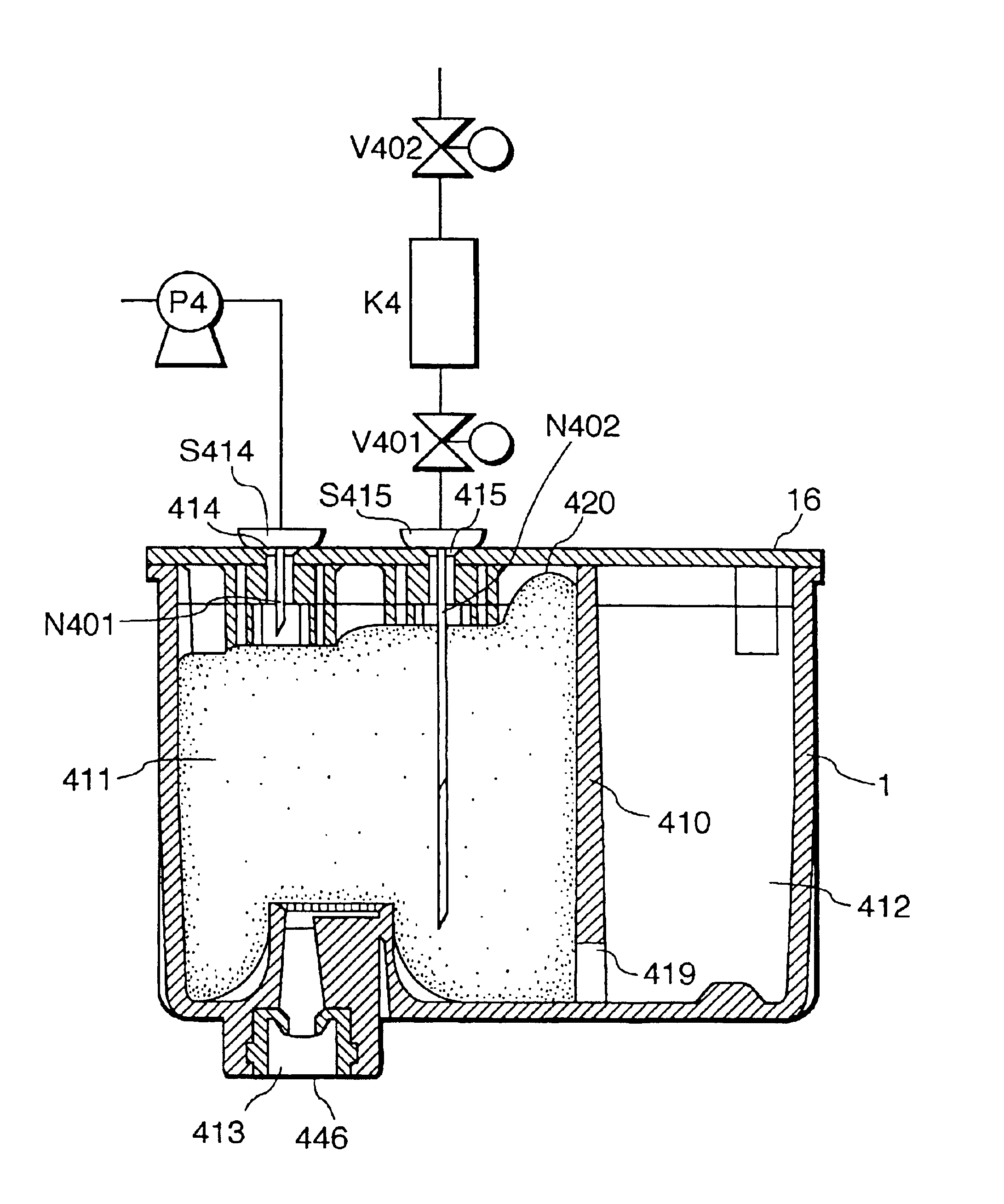
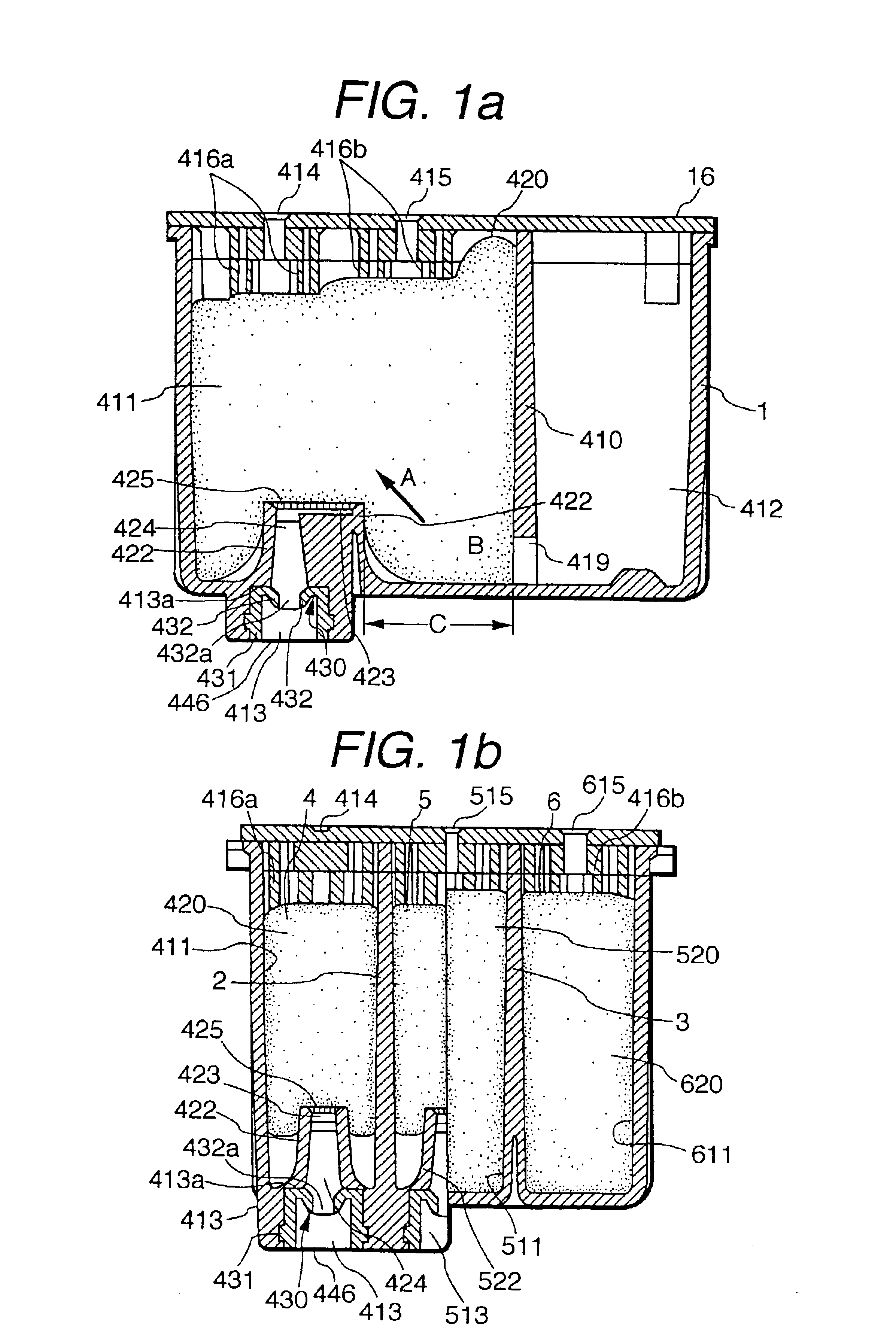
Referring first to FIGS. 1a and 1b, an ink cartridge constructed in accordance with the invention is shown. In FIGS. 1a and 1b, reference numeral 1 denotes a container main body, which is divided into three chambers 4, 5, 6 by partition plates 2, 3. Each of the chambers 4, 5, 6 is further divided into a foam chamber and an ink chamber by a partition, only foam chamber 411, ink chamber 412 and partition 410 of chamber 4, being visible in FIG. 1a. The remaining chambers 5 and 6 are essentially identical to chamber 4, foam chambers 511 and 611 of chambers 5 and 6 being visible in FIG. 1b. Each foam chamber 411, 511, 611 is designed to accommodate a respective porous body 420, 520, 620, made of an elastic material that is suitable for absorbing ink, and each ink chamber as exemplified by ink chamber 412 is designed to directly contain liquid ink. The volumes of the porous bodies 420, 520, 620 before insertion in the respective foam chambers 411, 511, 611 are larger than the capacity of ...

third embodiment

Reference is now made to FIG. 7 which depicts a packing member 730 for sealing ink supply needle 50 constructed in accordance with the invention. Elements similar to those in the previous embodiments are given like reference numerals. Packing member 730 includes a first annular seal 70, a second annular seal 71, and a bush 72. Seal 70 has a circular cross-section and is an elastic member that abuts innermost stepped portion 13a of ink supply port 13. Seal 71 has a circular cross-section and is an elastic member that is located on the film 46 side of seal 70. Bush 72 is provided to fix these two seals 70 and 71 to ink supply port 13, with seals 70 and 71 being maintained in elastic contact with each other. The inner diameter of each of the two seals 70 and 71 is selected so as to be slightly smaller than the outer diameter of ink supply needle 50 and the outer diameter of each of the seals 70 and 71 is selected so as to be slightly larger than the inner diameter of ink supply port 13...


PUM


Abstract

An ink cartridge including: an ink chamber for retaining liquid ink; a foam chamber maintained in fluid communication with the ink chamber through a communication hole. An ink supply port for supplying ink from a porous body accommodated in the foam chamber to a recording head is provided. The portion of the foam body confronting the ink supply port is compressed by the ink supply port. The ratio between the amount of ink initially charged in the ink chamber and that of ink absorbed in the porous body is in the range from 1:1 to 1:3. When a cartridge uses more than one color of ink for printing in color, a plurality of foam and ink cartridges are used. The cartridge is filled under reduced pressure while the interior of the cartridge is further evacuated before filling with ink.

Description

BACKGROUND OF THE INVENTIONThe invention relates generally to an ink cartridge and a method of charging ink into the cartridge and more specifically to an ink cartridge and a method of charging ink into the cartridge suitable for an ink jet printer in which a carriage carries an ink jet recording head and an ink cartridge and in which the ink is replenished by replacing the cartridge.In an ink jet printer in which the carriage carrying the ink jet recording head also carries an ink container, measures are taken to prevent pressure fluctuations of the ink due to the oscillation of the ink caused by the movement of the carriage, and defective printing due to foaming. That is, as proposed in Laid-open European Patent Publication No. 581531, the ink container of an ink jet printer is divided into two regions. A porous body is accommodated in a region on the recording head side, and ink is contained in the other region.Such structure is advantageous in obviating inconvenience caused by t...

Claims


Application Information

Patent Timeline
IPC IPC(8): B41J2/175
CPCB41J2/17506B41J2/17553B41J2/17513
Inventor KOBAYASHI, TAKAOSHINADA, SATOSHIUSUI, KIYOFUMIHIRAIDE, SHOICHIKOSHINO, KAZUOMIYAZAWA, HISASHIMOCHIZUKI, SEIJIMIYAZAWA, YOSHINORISUZUKI, TAKASHIYANAGIDA, EIKO
Owner SEIKO EPSON CORP
Why Eureka
Try Eureka