Ballistic resistant cap nut

a technology of ballistic resistance and cap nut, which is applied in the direction of bolts, drilling pipes, vehicle safety arrangments, etc., can solve the problems of not being able to disassemble from the passenger cabin side of the flight deck door, not being able to resist tampering, and being heavier than needed

Inactive Publication Date: 2005-02-15
THE BOEING CO
View PDF14 Cites 18 Cited by
  • Summary
  • Abstract
  • Description
  • Claims
  • Application Information

AI Technical Summary

Benefits of technology

The present invention is directed to a ballistic resistant cap nut used in a fastener system for securing together ballistic resistant doors and panels in an aircraft. As will be described, the fastener system generally comprises a cap nut and bolt or screw, where the cap nut is arranged on the passenger cabin side of a flight deck door. The cap nut is of sufficient thickness to meet the FAA ballistic criteria. In one preferred form, the ballistic resistant cap nut comprises an outside surface that allows the nut to be held while tightening. In another preferred form, the present invention provides a ballistic resistant cap nut with a shoulder on its mating face that contacts a surface of a mounting panel to which the ballistic resistant cap nut is secured. The shoulder, when in contact with the surface of the mounting panel, inhibits rotation of the cap nut when the fastener element is fully installed. The shoulder thus provides a tamper proof feature to the ballistic resistant cap nut so that an individual on the passenger cabin side of the door cannot tamper with the fastener system.

Problems solved by technology

Many of these fasteners were not designed to be tamper proof and may be heavier than need be.
While these fasteners may be adequate for their applications, fasteners for flight deck doors of a commercial passenger aircraft require a high strength-to-weight ratio, and also that they should not be able to be disassembled from the passenger cabin side of flight deck door.

Method used


Image

  • Ballistic resistant cap nut
  • Ballistic resistant cap nut
  • Ballistic resistant cap nut

Examples


Embodiment Construction

The following description of the preferred embodiments is merely exemplary in nature and is in no way intended to limit the invention, its application, or uses.

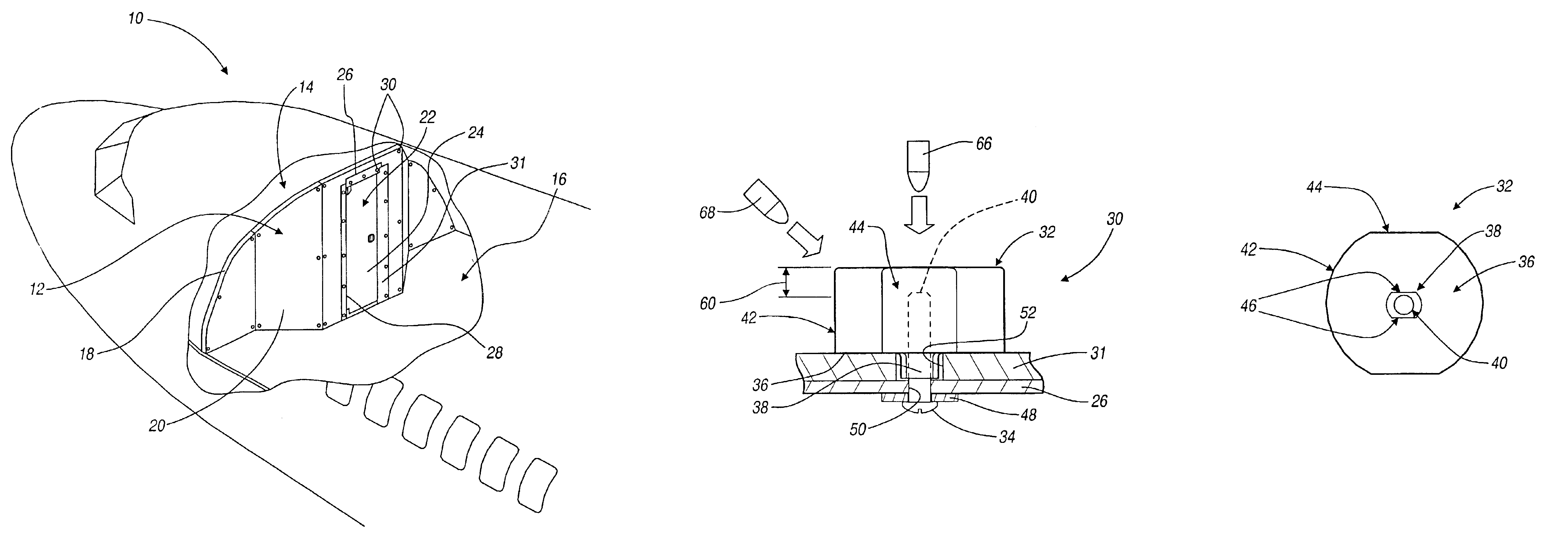
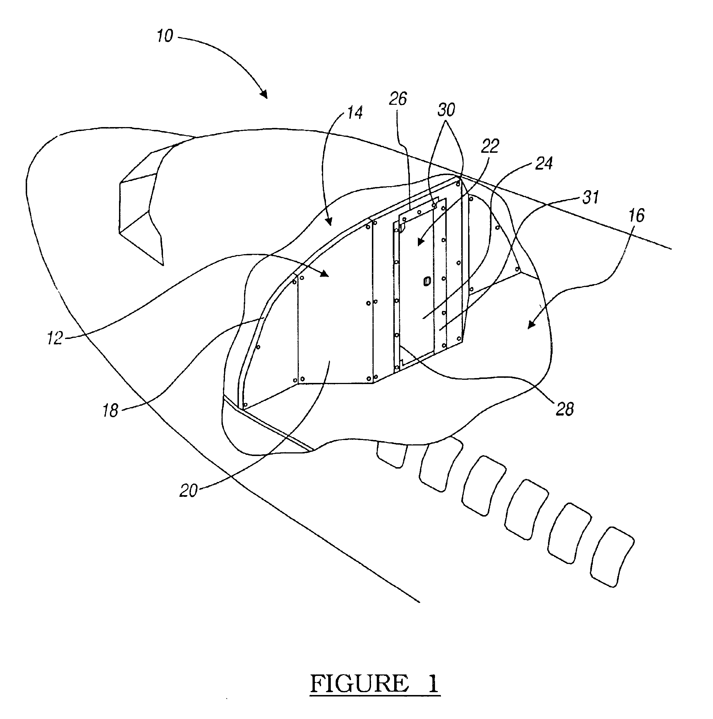
With reference to FIG. 1, an exemplary aircraft is generally indicated by reference numeral 10. The aircraft 10 includes a flight deck bulkhead 12 that separates a flight deck 14 from the passenger cabin 16. Flight deck bulkhead 12 includes a frame 18, panels 20, armor 31 and a door assembly 22 that are assembled to provide a barrier between the flight deck 14 and passenger cabin 16. Door assembly 22 includes a door 24, interconnected to a door frame 26 via a door hinge 28, for allowing control over access to the flight deck 14.

For ballistic and intrusion resistant applications, door assembly 22 and panel 20 may be strengthened with ballistic resistant materials. Generally, panel 20 and door frame 26 are overlapped by armor 31 to improve ballistic and intrusion resistance for flight deck bulkhead 12 and door assembly 22. A pl...


PUM


Abstract

A self locking fastener system is disclosed for light-weight ballistic resistant applications. The fastener system includes a ballistic resistant cap nut with an integral shoulder. The shoulder is formed onto the mating surface of the cap nut and is keyed to lock with a cut-out in a structural member to which the fastener system is secured. In a commercial aircraft, the cap nut is located on the passenger cabin side of the ballistic resistant flight deck door and prevents tampering therewith that might otherwise lead to disassembly or damage to the fastener system and degrade the ballistic resistance of the door assembly. Thus provided, the fastener system is resistant to removal by manipulation of the cap nut as well as damage from ballistic projectiles. The shoulder of the cap nut increases the shear area of the fastener along the plane of the mating surface thereby enhancing the fastener's resistance to shear loading. The cap nut is constructed of titanium or stainless steel.

Description

FIELD OF THE INVENTIONThe present invention relates to a ballistic resistant cap nut used in a fastener system for use in securing ballistic resistant panels and doors to frame members within an aircraft.BACKGROUND OF THE INVENTIONThe Federal Aviation Administration has issued requirements that flight decks of commercial aircraft meet new ballistic and intrusion criteria. Interior components such as flight deck doors and panels have been reinforced with ballistic resistant materials to comply with these mandated requirements. In aircraft design, factors such as pay-load capacity, fuel economy and safety are important considerations. Therefore, materials are generally selected that provide a high strength-to-weight ratio.A typical fastener for ballistic proof and armored panels is disclosed in U.S. Pat. No. 5,438,908. Some ballistic proof panels have specialized fasteners as disclosed in U.S. Pat. No. 5,600,084. Many of these fasteners were not designed to be tamper proof and may be ...

Claims


Application Information

Patent Timeline
Patent Type & Authority Patents(United States)
IPC IPC(8): F16B41/00F16B37/14F16B33/00F16B37/00F41H5/013F41H5/00
CPCF16B33/002F16B37/14F16B41/005F41H5/013Y10T403/1691Y10T403/18Y10T403/75Y10T403/16
Inventor MELBERG, DAVID S.KUNDA, JAMES J.
Owner THE BOEING CO
Why Eureka
Try Eureka