Mixed tuned hybrid bucket and related method

a hybrid bucket and hybrid technology, applied in the field of composite buckets, can solve the problems of reduced reliability, higher disk stress, low performance, etc., and achieve the effect of suppressing the aero-elastic response and adversely affecting the aerodynamic properties of the buck

Inactive Publication Date: 2005-02-15
GENERAL ELECTRIC CO
View PDF10 Cites 30 Cited by
  • Summary
  • Abstract
  • Description
  • Claims
  • Application Information

AI Technical Summary

Benefits of technology

This invention proposes a means of suppressing the aero-elastic response of a bucket or blade row (continuously coupled or free-standing) via mixed-tuning of the natural frequencies of the blades or buckets within the row. Specifically, this patent utilizes the hybrid bucket concept as disclosed in U.S. Pat. No. 5,931,641, but extends that concept to include optimization of internal pocket configurations within the airfoil portions of the buckets so as to produce, in the exemplary embodiment, two groups or populations of buckets, each with the same external aerodynamic shape and profile, but with different internal rib and / or pocket geometries that produce different bucket resonant frequencies. The pockets within the airfoil portions of the buckets are preferably filled with a polymer filler material that also forms one face of the airfoil portion of the bucket. By intentionally altering the natural frequencies of the two groups of buckets, the buckets may be purposefully and logically assembled so as to utilize this inherent difference in natural resonant frequencies as a means of damping the system response to synchronous and non-synchronous vibrations, without adversely affecting the aerodynamic properties of the buckets.
Because an overall weight reduction of up to about 30% in the bucket is achievable with hybrid buckets, attachment stresses can be reduced and reliability improved, without changing the aerodynamic characteristics of the airfoil portion.
In another aspect, the invention relates to a steam turbine rotor wheel comprising a row of buckets secured about a circumferential periphery of the wheel, the row of buckets including two groups of buckets, arranged in an alternating pattern about the periphery of the wheel, each group having discrete means for reducing amplitude of vibration in the row of buckets.

Problems solved by technology

This increasing section area of the bucket at lower spans contributes to excessive flow blockage at the root and thus lower performance.
The weight of the bucket contributes to higher disk stresses and thus to potentially reduced reliability.

Method used


Image

  • Mixed tuned hybrid bucket and related method
  • Mixed tuned hybrid bucket and related method
  • Mixed tuned hybrid bucket and related method

Examples


Embodiment Construction

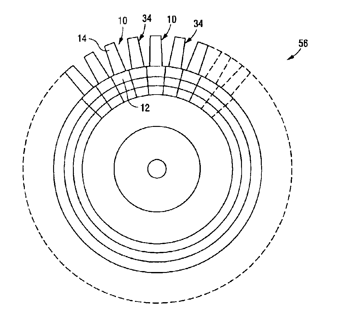
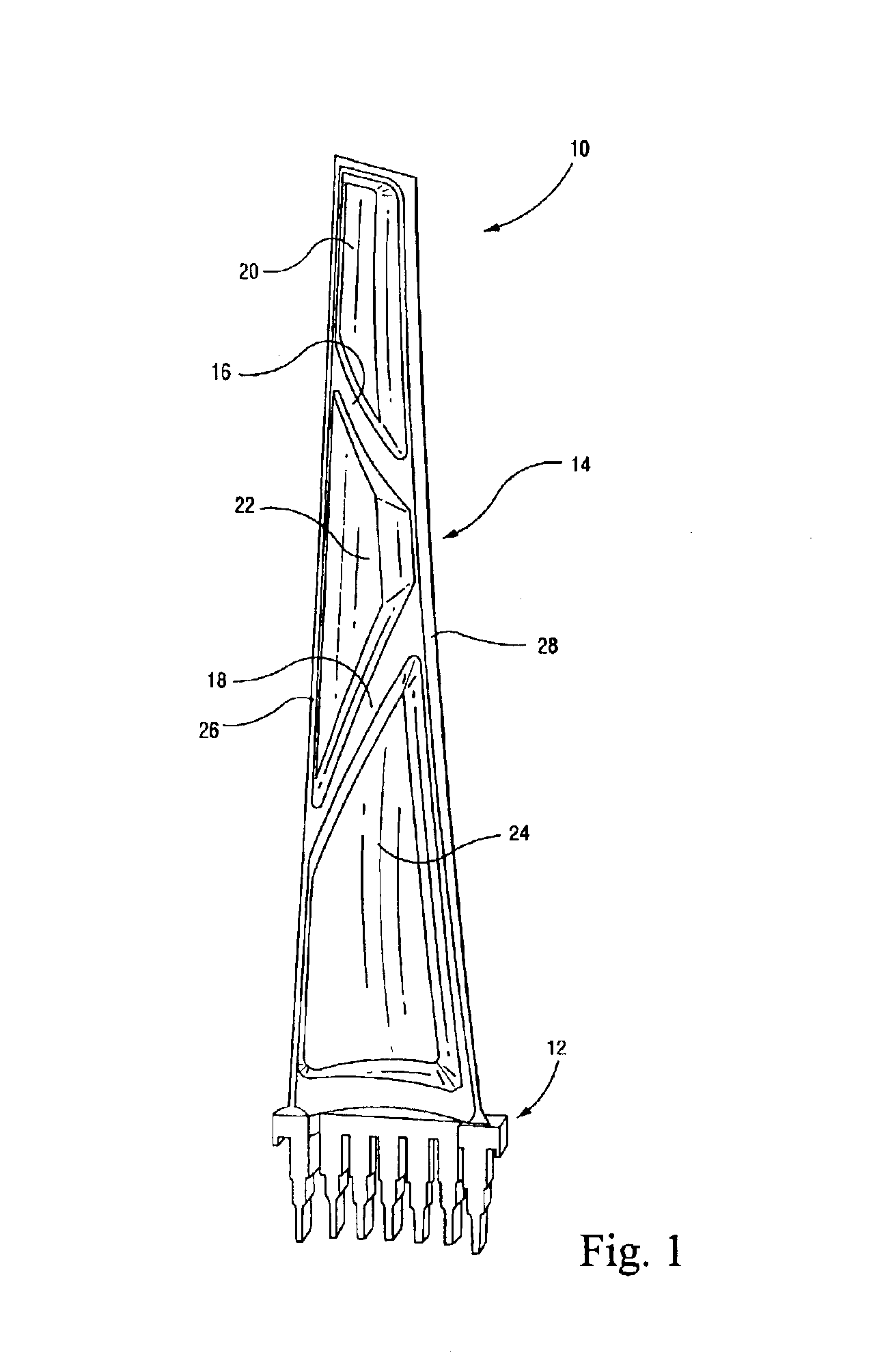
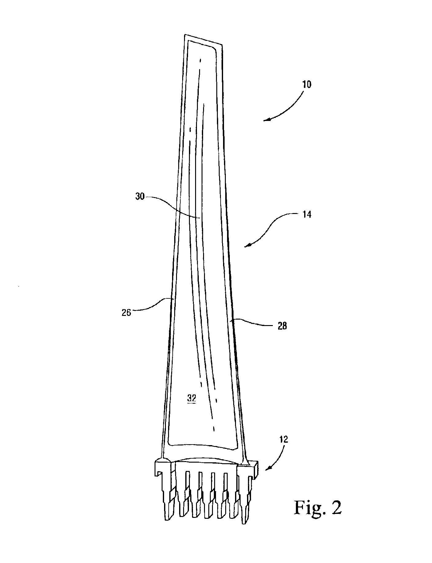
With reference to FIG. 1, a steam turbine bucket 10 is shown in partially manufactured form. The bucket 10 includes a shank portion 12 and an airfoil portion 14. This invention is concerned with the airfoil portion that is preferably constructed of steel or titanium but other suitable materials include aluminum, cobalt or nickel. Ribs 16, 18 are integrally cast with the airfoil portion to form discrete pockets 20, 22 and 24. It will be appreciated, however, that the ribs do not extend flush with the side edges 26, 28 of the airfoil portion. The rib height may in fact vary according to specific applications. Polymer based filler material 30 as described in U.S. Pat. No. 5,931,641 is cast-in-place over the pressure side of the airfoil, filling the pockets 20, 22 and 24 and covering the ribs to thereby form a smooth face 32 on the pressure side of the bucket, as shown in FIG. 2. Specifically, the filler material 30 may consist essentially of an elastomer, such as poly(dimethylsiloxane)...


PUM


Abstract

A steam turbine rotor wheel includes a plurality of buckets secured about a circumferential periphery of the wheel, each bucket comprising a shank portion and an airfoil portion, the plurality of buckets including two groups of buckets having respective different predetermined resonant frequencies. A method of reducing vibration in a row of buckets on a steam turbine rotor wheel includes a) providing a first group of buckets with a first predetermined natural frequency range; b) providing a second group of buckets with a second predetermined natural frequency range different than the first predetermined natural frequency range; and c) assembling buckets of the first and second groups of buckets in alternating fashion on the rotor wheel.

Description

BACKGROUND OF INVENTIONThis invention relates generally to steam turbine buckets (or blades) and, more particularly, to composite buckets specifically tuned to provide different predetermined frequency damping characteristics and improved system damping.Steam turbine buckets operate in an environment where they are subject to high centrifugal loads and vibratory stresses. Vibratory stresses increase when bucket natural frequencies become in resonance. The magnitude of vibratory stresses when a bucket vibrates in resonance is proportional to the amount of damping present in the system (damping is comprised of material, aerodynamic and mechanical components), as well as the vibration stimulus level. For continuously coupled buckets, the frequency of vibration is a function of the entire system of blades in a row, and not necessarily that of individual blades within the row.At the same time, centrifugal loads are a function of the operating speed, the mass of the bucket, and the radius...

Claims


Application Information

Patent Timeline
Patent Type & Authority Patents(United States)
IPC IPC(8): F01D5/14F01D5/16F01D5/10F01D5/28
CPCF01D5/147F01D5/16Y10S416/50F05D2300/43F05D2300/615F05D2250/291
Inventor BARB, KEVIN JOSEPH
Owner GENERAL ELECTRIC CO
Why Eureka
Try Eureka