Dental implants and dental implant/prosthetic tooth systems

Inactive Publication Date: 2005-02-15
ELIAN NICHOLAS
View PDF36 Cites 119 Cited by
  • Summary
  • Abstract
  • Description
  • Claims
  • Application Information

AI Technical Summary

Benefits of technology

In another embodiment of the embodiment of the invention, a dental implant is provided having a buccal side for being aligned with the buccal side of the jaw bone, a lingual side for being aligned with a lingual side of the jaw bone and interproximal sides between the buccal and lingual sides. The

Problems solved by technology

The upper jaw bone, however, is very soft and it is common for dental implants in the upper jaw to lack primary stability.
While screwing self-tapping and pretapping implants into the bone generally improves the mechanical coupling between the implant and bone, it has been found that in the soft bone of the upper jaw, the rotation of both the self-tapping and pre-tapping implants may destroy the grooves, preventing tight coupling between the implant and the bone.
Mechanical solutions to achieving primary stability and osteointegration have generally ignored the natural shapes of the root and crown of the natural tooth being replaced and have not conformed to the natural relationship between the tooth and the jaw bone, resulting in adverse immunological responses by the jaw bone which both weakens primary stability and osteointegration, and sacrifices aesthetics.
For example, it has been found that the failure of interface between the dental implant and the prosthetic tooth to conform to the shape and location of the cemento-enamel junction between the crown and root of the tooth being replaced causes an adverse immunological response by the bone to the dental implant, resulting in bone resorbtion.
This can weaken the bond between the implant and the bone and leave pockets which can collect pla

Method used


Image

  • Dental implants and dental implant/prosthetic tooth systems
  • Dental implants and dental implant/prosthetic tooth systems
  • Dental implants and dental implant/prosthetic tooth systems

Examples


Example

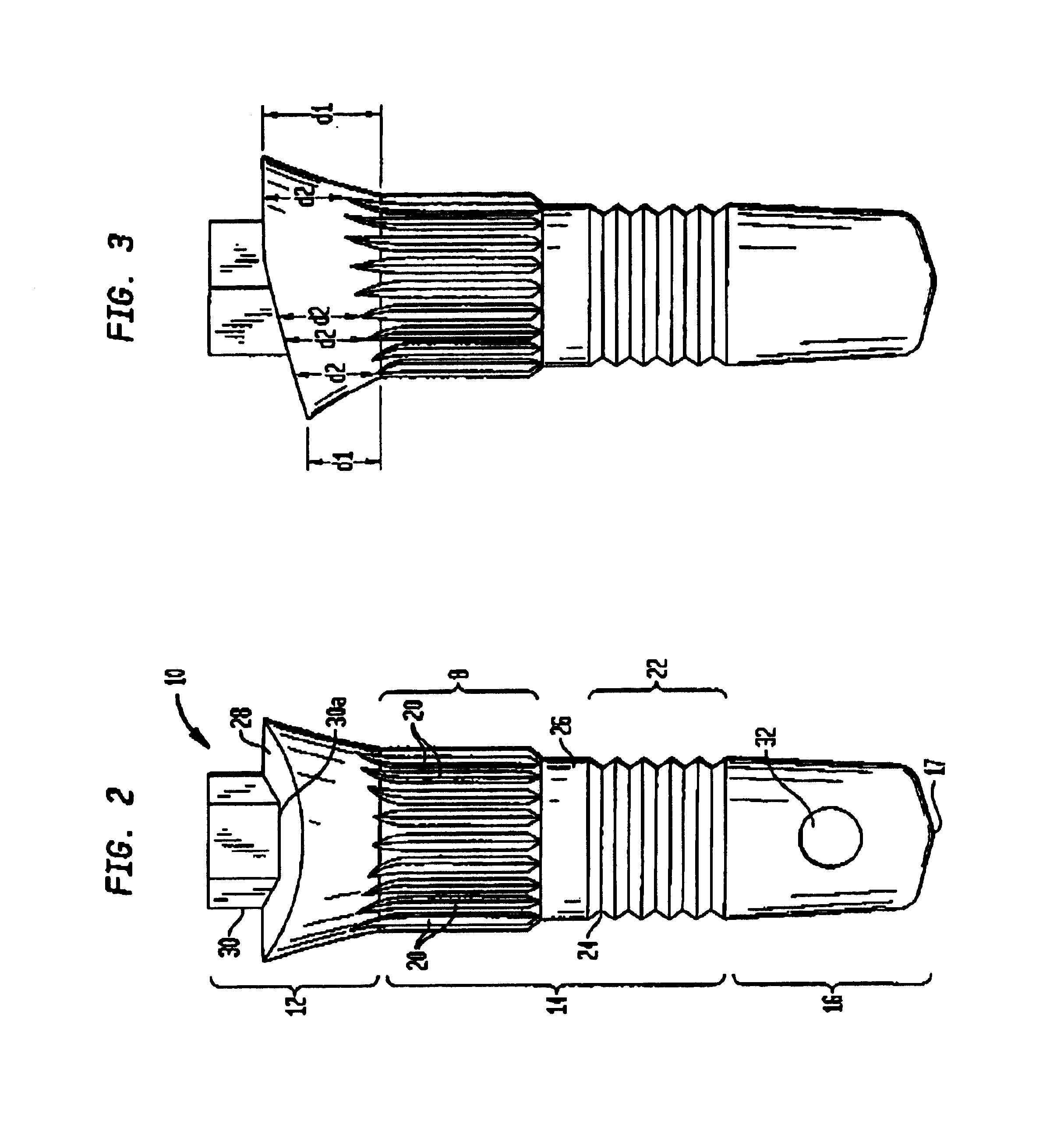
FIG. 2 is a side view of the buccal side of a dental implant 10 in accordance with one embodiment of the present invention. FIG. 3 is a side view of the proximal side of the dental implant 10 of FIG. 2. The dental implant 10 is preferably a single piece with a head portion 12, a body portion 14 and a tip portion 16, extending along a longitudinal axis “L”.

The body portion is cylindrical and includes a first section 18 with a plurality of longitudinal grooves 20 substantially parallel to the longitudinal axis L of the implant 10, proximate the head portion 12. Preferably, at least some of the longitudinal grooves 20 extend into the head portion 12. The depth of each groove 20 may be about 1 mm. The outer diameter of the first section is preferably from about 3.75 mm to about 5.00 mm depending on the type of tooth being replaced and the position of the tooth in the mouth.

The cylindrical body portion 14 includes a second section 22 with a circumferential spiral thread 24. Preferably, t...


PUM


Abstract

A one-piece dental implant having a longitudinal axis comprises a head portion at a first end of the implant, a tip portion at a second end of the implant and a body portion between the head portion and the tip portion. The body portion has a first portion proximate the head portion with a plurality of longitudinal grooves substantially parallel to the longitudinal axis and a second portion proximate the tip portion having a substantially circumferential groove, wherein the outer diameter of the first portion is greater than the outer diameter of the second portion. The first and second portions are for being embedded in the jaw bone. The dental implant is preferably dimensioned to conform to the natural shape of the cervical ⅓ of the root of the tooth being replaced, and to the natural relationship between the cemento-enamel junction of the tooth being replaced and to minimize adverse immunological responses by the jaw bone during healing, thereby improving the aesthetic appearance of the implant and prosthetic tooth attached thereto. A dental implant and prosthetic tooth system is also disclosed, wherein the prosthetic tooth conforms to the shape of the cervical ⅓ of the crown of the tooth being replaced. A method for implanting a dental implant through use of a reference, is also disclosed.

Description

BACKGROUND OF THE INVENTIONDental implants are inserted into the base of the jaw and have a portion protruding through the mucous gum tissue for providing attachment anchorage for artificial teeth. An artificial tooth may be attached directly to the implant, or to an abutment connected to the implant. Dental implants are becoming increasingly popular alternatives to dentures.Dental implants have been used in the hard bone of the lower jaw with great success. The upper jaw bone, however, is very soft and it is common for dental implants in the upper jaw to lack primary stability.There are three major types of dental implants: 1) press-fit; 2) self-tapping; and 3) pre-tapping. The press-fit type implants are inserted into holes drilled into the bone without rotation. Press-fit implants do not couple tightly to the soft bone of the upper jaw.Self-tapping and pre-tapping type implants have horizontal threads for being screwed into holes drilled into the jaw-bone, for better mechanical c...

Claims


Application Information

Patent Timeline
IPC IPC(8): A61C8/00
CPCA61C8/0006A61C8/0012A61C8/0018A61C8/0022A61C8/0077A61C8/0013
Inventor ELIAN, NICHOLAS
Owner ELIAN NICHOLAS
Why Eureka
Try Eureka