
Control for watercraft propulsion system

a control system and watercraft technology, applied in marine propulsion, propulsion transmission, vessel construction, etc., can solve the problems of changing the turning angle of the throttle and making the rider uncomfortabl

Inactive Publication Date: 2005-02-15
YAMAHA MARINE KK
View PDF7 Cites 40 Cited by
  • Summary
  • Abstract
  • Description
  • Claims
  • Application Information

AI Technical Summary

Benefits of technology

One aspect of at least one of the inventions disclosed herein includes the realization that a modified engine speed value can be more in proportion to the watercraft speed than actual engine speed, and thus provide an approximately proportional indicator of watercraft speed, under at least some circumstances. For example, an engine speed value can be modified such that the value of the modified engine speed value changes more slowly than the actual engine speed. Similarly, the watercraft speed, during positive and negative acceleration, changes more slowly than can the engine speed. Thus, the engine speed itself can be used as a basis for estimating watercraft speed for engine control operations, thereby avoiding the use of a sensor that directly detects watercraft speed. This is advantageous because water speed sensors are prone to clogging and damage because they are in contact with the water in which the watercraft operates.
In accordance with another aspect of at least one of the inventions disclosed herein, a method of providing additional steering force for a watercraft is provided. The method includes detecting a propulsion request from an operator of the watercraft, detecting a steering direction request from the operator of the watercraft, and detecting a speed of an engine of the watercraft. The method also includes increasing a power output of the engine to an elevated power output level that is greater than the power output level corresponding to the propulsion request, and returning the power output of the engine to the level corresponding to the propulsion request after a delay after the engine speed falls below a predetermined engine speed value.

Problems solved by technology

When the throttle is released, the natural feeling of on-throttle turning can change and make the rider uncomfortable while maneuvering the watercraft.

Method used


Image

  • Control for watercraft propulsion system
  • Control for watercraft propulsion system
  • Control for watercraft propulsion system

Examples


Embodiment Construction

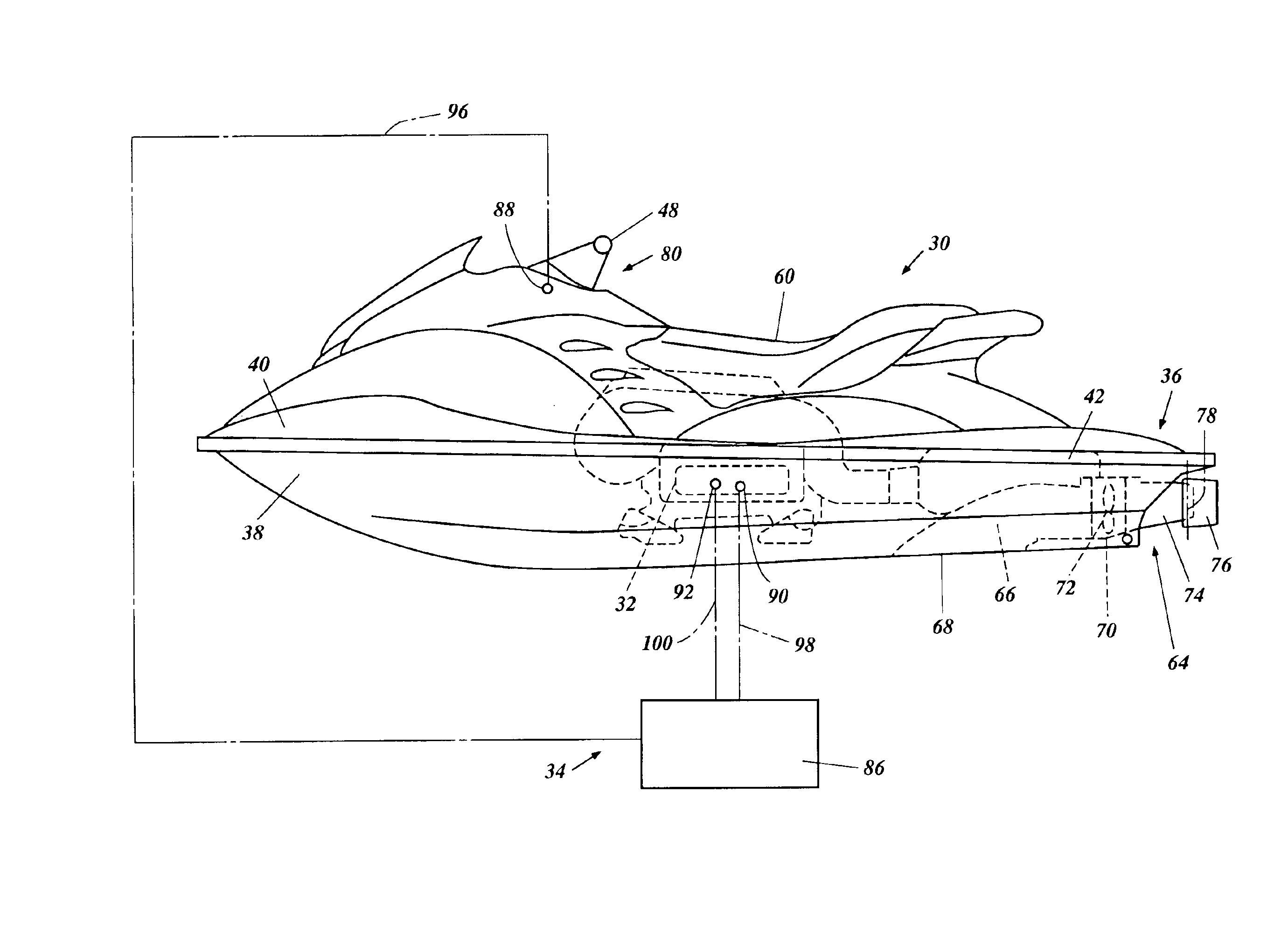
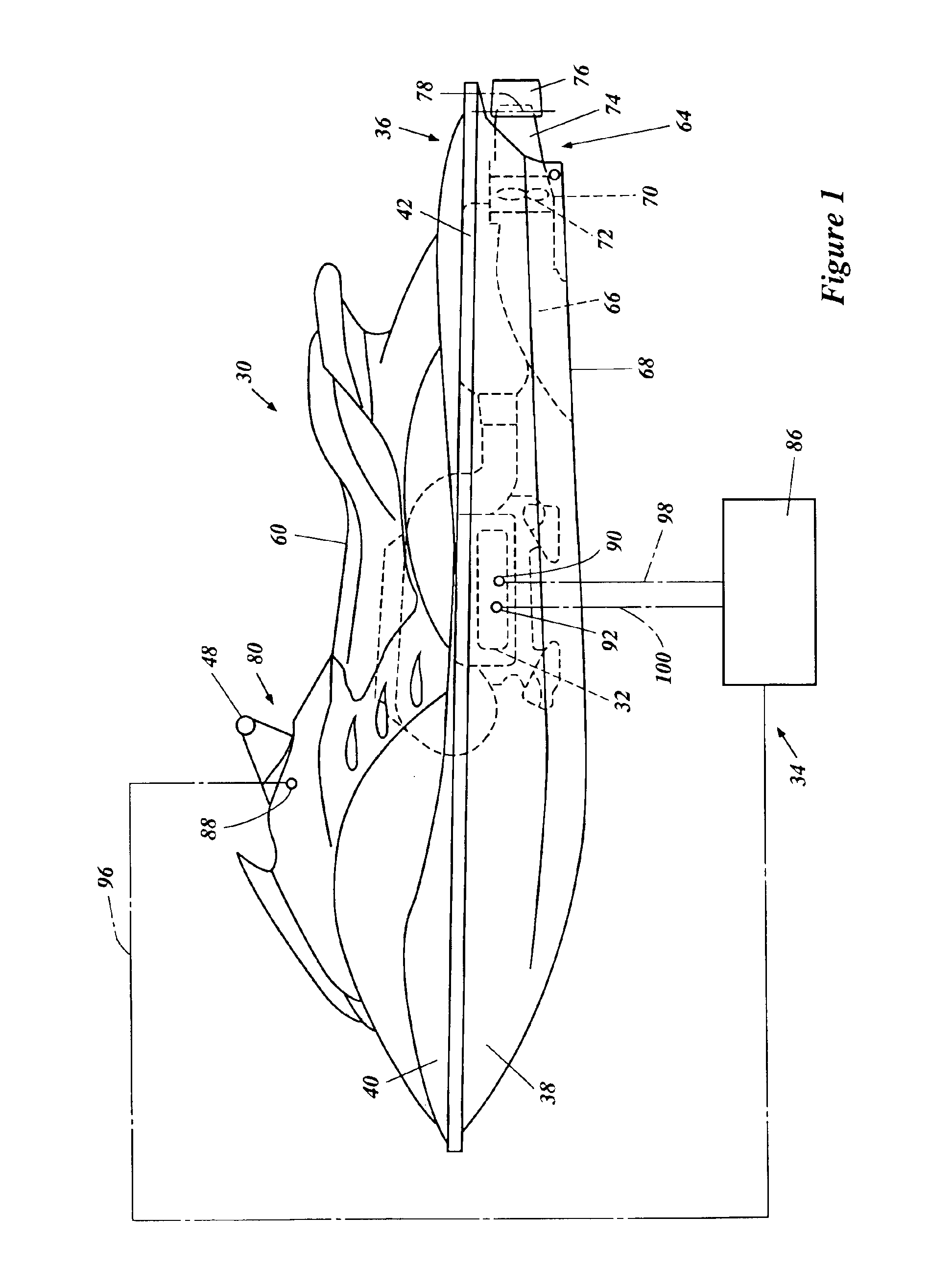
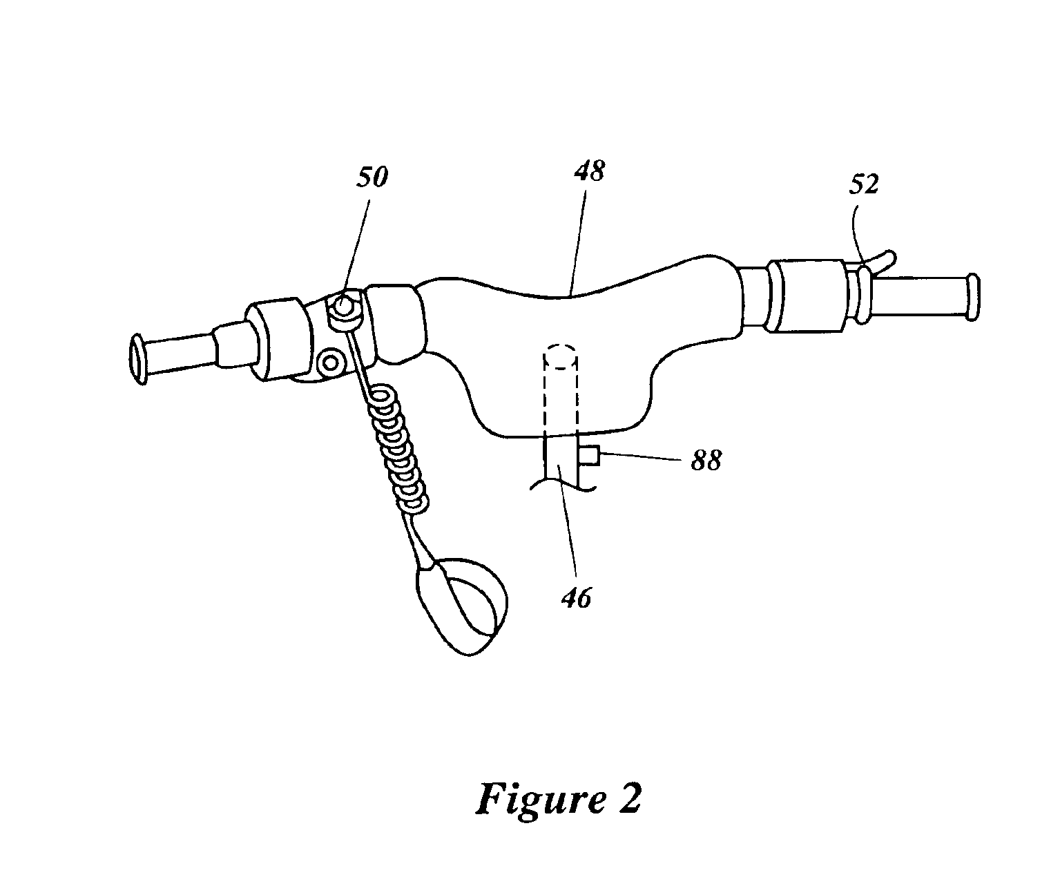
With primary reference to FIG. 1 and additionally to FIGS. 2 and 3, an overall configuration of a personal watercraft 30 is described below. The watercraft 30 employs an internal combustion engine 32 and an engine control system 34 configured in accordance with an embodiment of at least one of the inventions disclosed herein. This engine control system 34 has particular utility with a personal watercraft, and thus is described in the context of the personal watercraft 30. The control system however can be applied to other vehicles such as, for example small jet boats.

The personal watercraft 30 includes hull 36 having a lower hull section 38 and an upper hull section or deck 40. The lower hull section 38 can include one or more inner liner sections to strengthen the hull or to provide mounting platforms for various internal components of the watercraft. The hull sections 38 and 40 are made of, for example, a molded fiberglass reinforced resin or a sheet molding compound. The lower hu...


PUM


Abstract

An engine output control device is configured to detect an actual engine speed and to determine a modified engine speed based on the actual engine speed that is more in proportion to the speed of the watercraft than the actual engine speed. The modified engine speed can be used to control the output of the engine so as to provide a more natural feeling for the operator of the watercraft. The modified engine speed can also be used as an indication of the speed of the watercraft. As such, the modified engine speed can also be used to determine the extent to which the output of the engine can be raised to provide additional thrust for steering purposes.

Description

1. Field of the InventionThe present application relates to a control system for an engine of a watercraft, and in particular, to a control system which relates to engine operation of a watercraft during turning.2. Description of the Related ArtPersonal watercraft have become very popular in recent years. This type of watercraft is quite sporting in nature and carries one or more riders. A hull of the personal watercraft commonly defines a rider's area above an engine compartment. An internal combustion engine powers a jet propulsion unit that propels the watercraft by discharging water rearwardly. The engine lies within the engine compartment in front of a tunnel, which is formed on an underside of the hull. The jet propulsion unit is placed within the tunnel and includes an impeller that is driven by the engine.A deflector or turning nozzle is mounted on the rear end of the jet propulsion unit for steering the watercraft. A steering mast with a handlebar is linked with the deflect...

Claims


Application Information

Patent Timeline
Patent Type & Authority Patents(United States)
IPC IPC(8): B63H21/00B63H21/22
CPCB63H21/213
Inventor KINOSHITA, YOSHIMASAITO, KAZUMASA
Owner YAMAHA MARINE KK
Learn More