Tube surface cleaning device

a cleaning device and tube technology, applied in the field of pipe fittings, can solve problems such as ineffective function, and achieve the effects of less strain on the wrist and fingers, less tiring, and easy rotation

Inactive Publication Date: 2005-02-15
LAWS RANDY D
View PDF11 Cites 7 Cited by
  • Summary
  • Abstract
  • Description
  • Claims
  • Application Information

AI Technical Summary

Benefits of technology

Many advantages flow from the present invention including that the device can be installed on tubing with mere fingertip action and very easily rotated by the operators palm which requires less strain on the wrist and fingers and is less

Problems solved by technology

Such tools have utility for many tube cleaning applications, particularly where the tube is fully accessible for cleaning and rotation of the cleaning mechanism, however, they do not function effectively in certain situations such as wher

Method used


Image

  • Tube surface cleaning device
  • Tube surface cleaning device
  • Tube surface cleaning device

Examples


Embodiment Construction

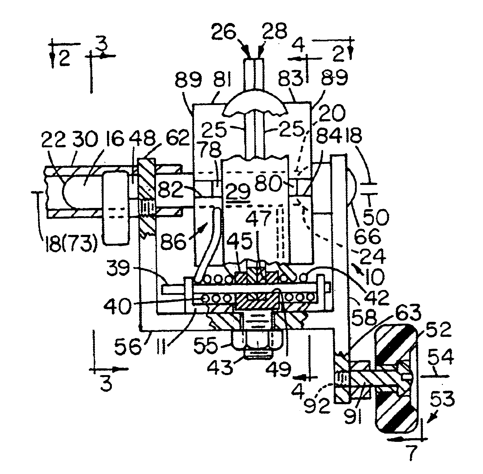
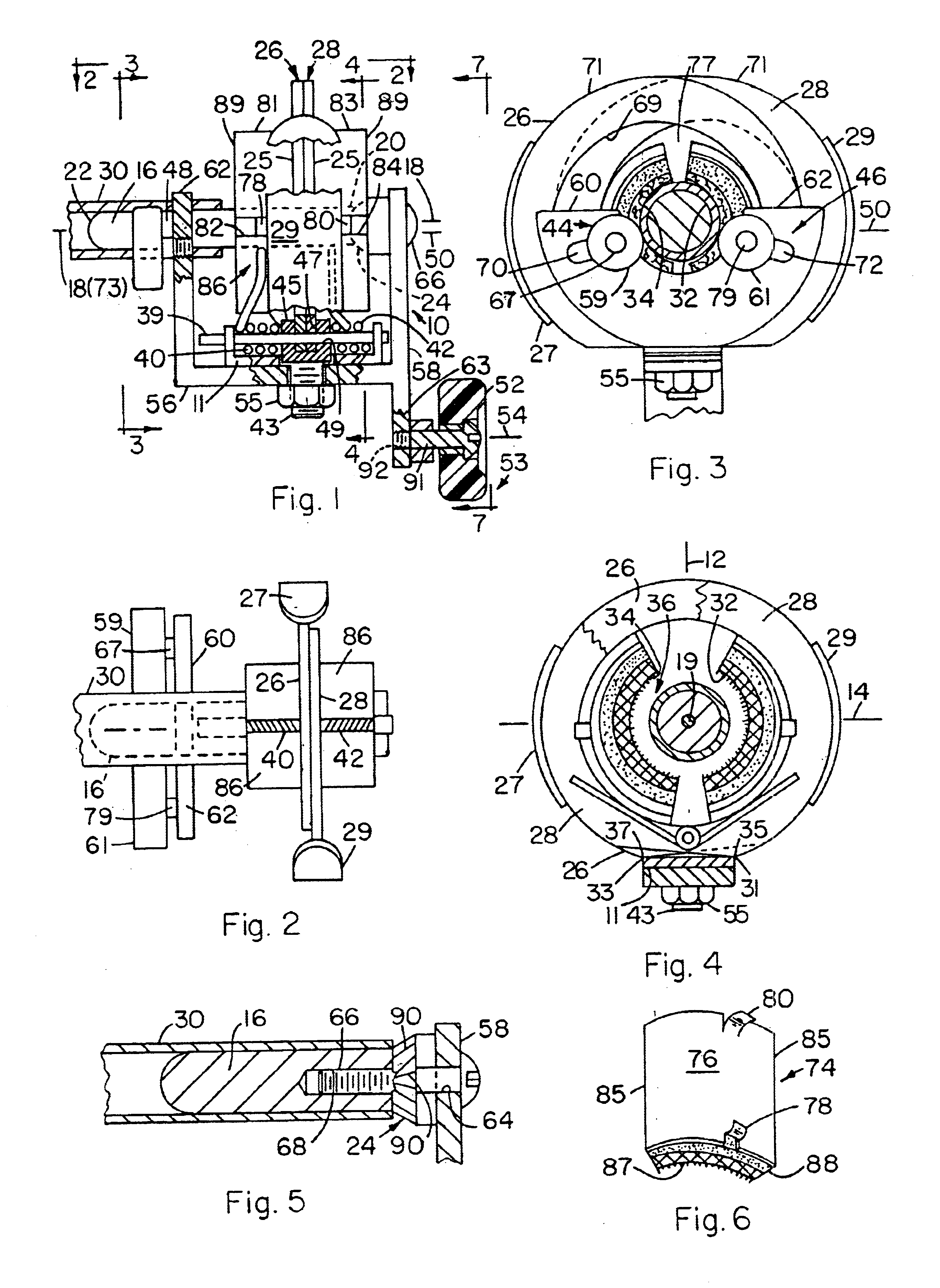
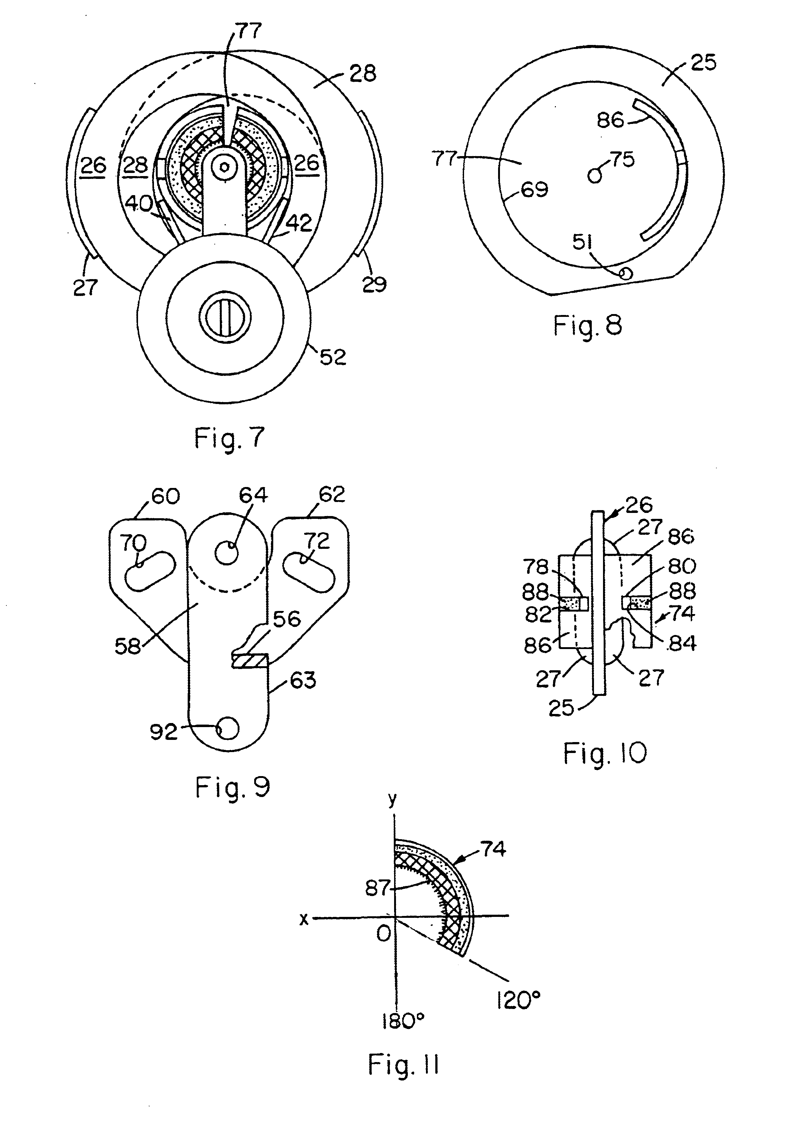
Referring to the drawings and with particular reference to the claims hereof, the present invention in one of its preferred embodiments is defined as a tube cleaning device comprising a frame means generally designated 10 having a vertical plane 12 and a horizontal plane 14, a work tube mandrel 16 fixed to said frame means and having a longitudinal axis 18 lying substantially thru the intersection 19 of said planes, said mandrel having a proximal end portion 20, a distal end portion 22, and a stop shoulder 24 adjacent said proximal end, a pair of opposing abrading jaw means 26,28 pivotally mounted on said frame means for pivotal motion of each jaw means toward and away from longitudinal axis 18 to close and open around the work tube 30, said jaw means having opposing abrasion surfaces 32,34 forming an abrasion cavity generally designated 36 having a median axis 73 and substantially encircling the proximal end portion 20 of said mandrel, spring means preferably comprising a pair of t...


PUM


Abstract

A tube cleaning device having a pair of jaws pivotally mounted on a frame and having opposed abrading surfaces defining an abrasion cavity, a mandrel fixed to the frame and extending axially thru the cavity for slidably receiving a tube end to be cleaned, spring structure forcing the abrading surfaces toward each other and laterally toward the mandrel, and a rotator knob on the frame for rotating the device in either direction around a tube end positioned on the mandrel.

Description

BACKGROUND OF THE INVENTION1. FieldIn the field of plumbing or pipe fitting it is common practice to abrade away oxidation, scale, and the like from the surfaces of copper or bronze tubing prior to soldering the tubing to various items such as T's, elbows, unions, or the like. If the tube surface is not properly cleaned, the solder which is to be “sweated” onto the tube and item will not form a watertight or gastight seal between the tube and item, and, in fact, will not form a joint at all in certain situations.2. Prior ArtHeretofore many tube cleaning tools have been proposed including those described in U.S. Pat. Nos. 3,568,376; 6,106,370; 6,393,645 B1; 5,168,660; 5,058,327; and 5,146,717. Such tools have utility for many tube cleaning applications, particularly where the tube is fully accessible for cleaning and rotation of the cleaning mechanism, however, they do not function effectively in certain situations such as where a tube end is located in fairly tight quarters where it...

Claims


Application Information

Patent Timeline
IPC IPC(8): B08B9/02B24B9/00
CPCB24B9/007B08B9/021
Inventor LAWS, RANDY D.
Owner LAWS RANDY D
Why Eureka
Try Eureka