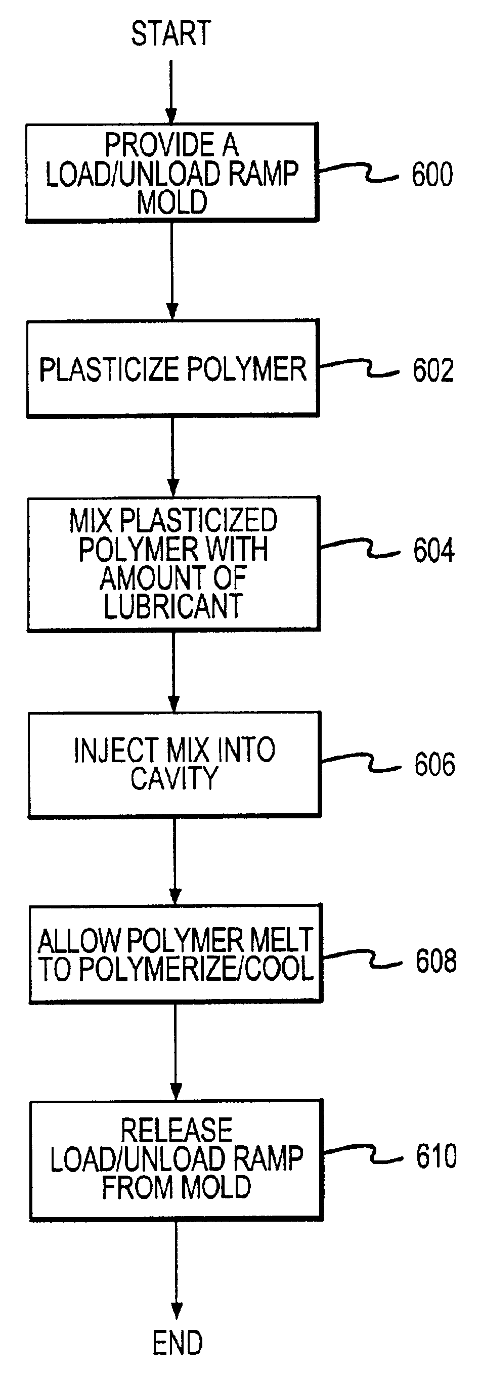
Method of fabricating a lubricant-integrated load/unload ramp for a disc drive
- Summary
- Abstract
- Description
- Claims
- Application Information
AI Technical Summary
Benefits of technology
Problems solved by technology
Method used
Image

Examples
Embodiment Construction
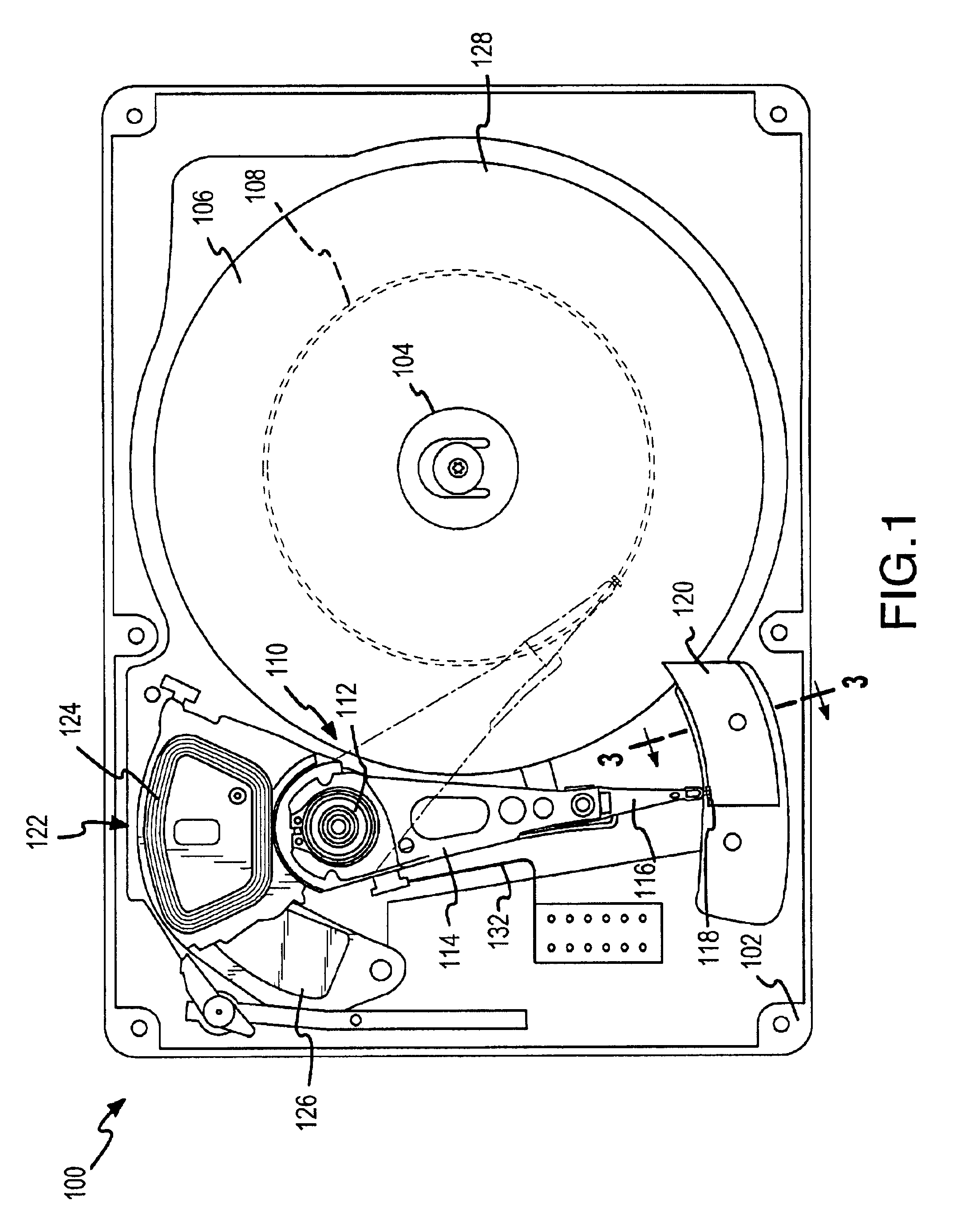
A disc drive 100 constructed in accordance with a preferred embodiment of the present invention is shown in FIG. 1. The disc drive 100 includes a base 102 to which various components of the disc drive 100 are mounted. A top cover (not shown) cooperates with the base 102 to form an internal, sealed environment for the disc drive in a conventional manner. The components include a spindle motor 104 which rotates one or more discs 106 at a constant high speed. Information is written to and read from tracks 108 on the discs 106 through the use of an actuator assembly 110, which rotates during a seek operation about a bearing shaft assembly 112 positioned adjacent the discs 106. The actuator assembly 110 includes a plurality of actuator arms 114 which extend towards the discs 106, with one or more flexures 116 extending from each of the actuator arms 114. Mounted at the distal end of each of the flexures 116 is a head 118 which includes an air bearing slider (not shown) enabling the head ...
PUM
| Property | Measurement | Unit |
|---|---|---|
| Fraction | aaaaa | aaaaa |
| Fraction | aaaaa | aaaaa |
| Thickness | aaaaa | aaaaa |
Abstract
Description
Claims
Application Information
 - R&D Engineer
- R&D Manager
- IP Professional
- Industry Leading Data Capabilities
- Powerful AI technology
- Patent DNA Extraction
Browse by: Latest US Patents, China's latest patents, Technical Efficacy Thesaurus, Application Domain, Technology Topic.
© 2024 PatSnap. All rights reserved.Legal|Privacy policy|Modern Slavery Act Transparency Statement|Sitemap