Time-domain reflectometer for testing terminated network cable

a technology of time-domain reflectometer and terminated network cable, which is applied in the direction of resistance/reactance/impedence, instruments, baseband system details, etc., can solve the problems of reducing the effectiveness of tdr test, not providing clear and simple testing solutions for cables connected to a network, and actually detrimental to testing terminated network cables

Active Publication Date: 2005-02-15
LINKRUNNER LLC
View PDF10 Cites 74 Cited by
  • Summary
  • Abstract
  • Description
  • Claims
  • Application Information

AI Technical Summary

Problems solved by technology

Unfortunately, prior art cable testers utilizing TDR circuits of the type depicted in FIG.
2 and described above, do not provide clear and simple testing solutions for cables that are connected to a network.
While this fixed impedance matching is preferable in most testing methodologies, it is actually detrimental when testing terminated network cables.
However, when the cable under test is terminated into a network, the mismatched impedance of the connection results

Method used


Image

  • Time-domain reflectometer for testing terminated network cable
  • Time-domain reflectometer for testing terminated network cable
  • Time-domain reflectometer for testing terminated network cable

Examples


Embodiment Construction

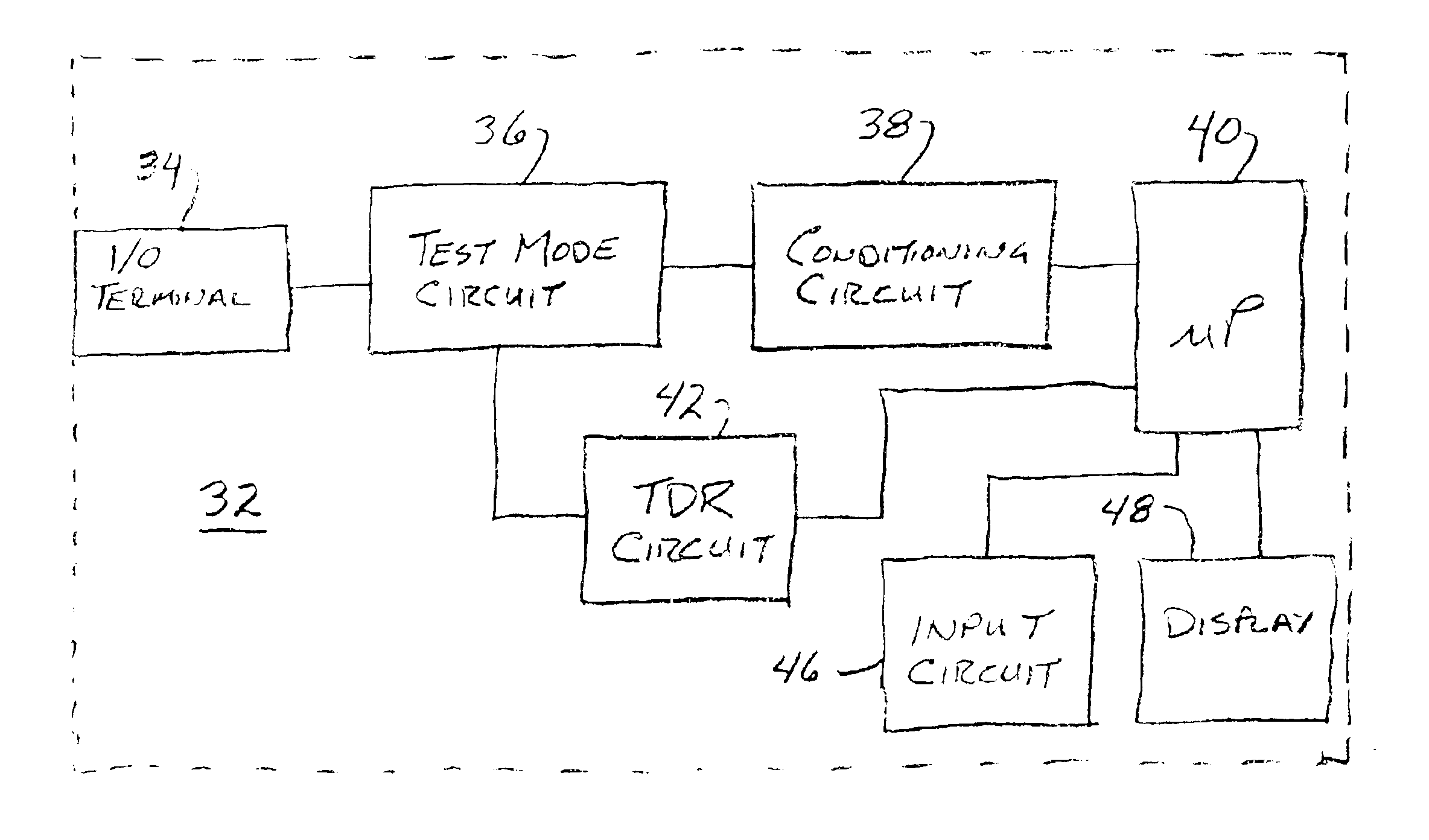
Turning now to FIG. 4 there is illustrated a block diagram of a cable tester 32 suitable for performing TDR testing. Cable testers, and their general operation, are well known by persons in the area of network testing and analysis. Accordingly, cable tester 32 is not described in detail, but rather is discussed in general terms to better allow the understanding of the present invention.

Cable tester 32 includes an input / output terminal 34 for coupling to the link cable which is to be tested. Typically, the instrument is not directly connected to the link cable, but is instead coupled to the cable by a test cable that runs from terminal 34 to the link cable. Terminal 34 is coupled to test mode circuit 36 which configures the tester for a particular test. Conditioning circuit 38 is connected to test mode circuit 36 and processor 40, and performs, among other tasks, conditioning, filtering and organizing of the signal and data passing between processor 40 and test mode circuit 36. Displ...


PUM


Abstract

A time domain reflectometer having a first impedance when in a first test mode and a second impedance when in a second test mode. The first impedance is substantially the same as the nominal characteristic impedance of a network link cable not connected to a network and the second impedance is substantially different from the impedance of a network link cable that is terminated into a network. A method for measuring the length of a terminated network cable includes the steps of determining that the network cable is terminated at a network, selecting a test mode suitable for testing the terminated network cable, and performing time domain reflectometry testing on the terminated network cable.

Description

BACKGROUND OF THE INVENTIONThis invention relates generally to time-domain reflectometry and more particularly to a time-domain reflectometry apparatus and method for testing a terminated network cable.In a network environment, such as Ethernet systems, devices are connected to the network by cables, commonly referred to as link cables. FIG. 1 illustrates a portion of a network where device 18, such as a computer or printer, is connected at node 16 to one end of link cable 14. The other end of link cable 14 is connected at node 12 to the network, which in FIG. 1 is represented by cable 10.Technicians troubleshooting networks need to test, among other network elements, the various link cables in the system. To verify that link cables meet specifications, technicians use cable test instruments, which have the ability to test, among other parameters, cable length. In an Ethernet system, for example, the length of a link cable is limited by system standards to a maximum of 100 meters. C...

Claims


Application Information

Patent Timeline
IPC IPC(8): G01R31/11G01R31/08H04L25/02
CPCG01R31/11
Inventor BOHLEY, THOMAS K.
Owner LINKRUNNER LLC
Why Eureka
Try Eureka