System for testing wiring characteristics

a technology for testing equipment and wiring characteristics, applied in the direction of fault location, measurement devices, instruments, etc., can solve the problems of low reliability of wiring harness troubleshooting systems, high cost and complexity of most such systems currently in use, and difficulty in finding intermittent problems, so as to reduce liability insurance

Inactive Publication Date: 2007-01-04
KRIGEL HENRICK YOUVAL
View PDF2 Cites 28 Cited by
  • Summary
  • Abstract
  • Description
  • Claims
  • Application Information

AI Technical Summary

Benefits of technology

[0014] The present invention provides an easy-to-use test system capable of troubleshooting several different types of faults within a wiring harness, such as intermittence and corrosion. In addition it can find the distance to the fault and pinpoint to the exact location of the problem.
[0021] The load apparatus consists of two portable, battery-operated units. One unit connects to one end of the harness; the other unit connects to the other end of the harness. The units control and monitor up to 128 wires for the ability of each wire to carry a load, adjustable by the user, up to 5 Amperes. It can be upgraded to provide even more current. The tester monitors the amount of current flowing in the wire, as well as the amount of voltage loss on the wire, thereby reflecting the quality of the wire and the connections, such as connectors and splices, and alerts the user by producing a fault condition. The user can test the wires by manually advancing to the next wire and observing the results of pass or fail, or setting the tester to the “Auto Mode” and “Stop On Fail,” which will automatically test the wires, and stop when a failure is found. This information may also be displayed on a hand-held unit, via wireless communication. This will allow the user to inspect the harness at its full length, wiggle it at any suspected location, and view the results on either the receiving unit or the portable hand held unit.
[0023] Because the present invention provides high current to the wires under test, the version used in the system described in FIG. 1 is limited to one wire only to eliminate the possibility of providing high currents to a harness installed inside the aircraft, and may be still connected to the LRU, even though, the system is using isolated return. This fact may also reduce the liability insurance the user may need to carry. For other applications, when a harness is being built outside of the aircraft, a full 128-wire embodiment may be used.

Problems solved by technology

There are few effective systems for troubleshooting wiring harnesses.
Most such systems currently in use are both extremely expensive and complex, designed to be utilized by at least two technicians positioned at either end of the wiring harness under investigation.
Intermittence problems account for close to 90% of wiring problems within aircraft, and are caused by aging wiring, wear and tear, and vibrations.
Finding intermittent problems are very difficult because it may be present during the flight but not on the ground.
By touching the wire bundles, the problem may temporarily disappear and not detected.
These problems are difficult to find and may take a very long time to be detected.
In a case of intermittent problem, the tests need to be repeated constantly until the failure occurs.

Method used


Image

  • System for testing wiring characteristics
  • System for testing wiring characteristics
  • System for testing wiring characteristics

Examples


Embodiment Construction

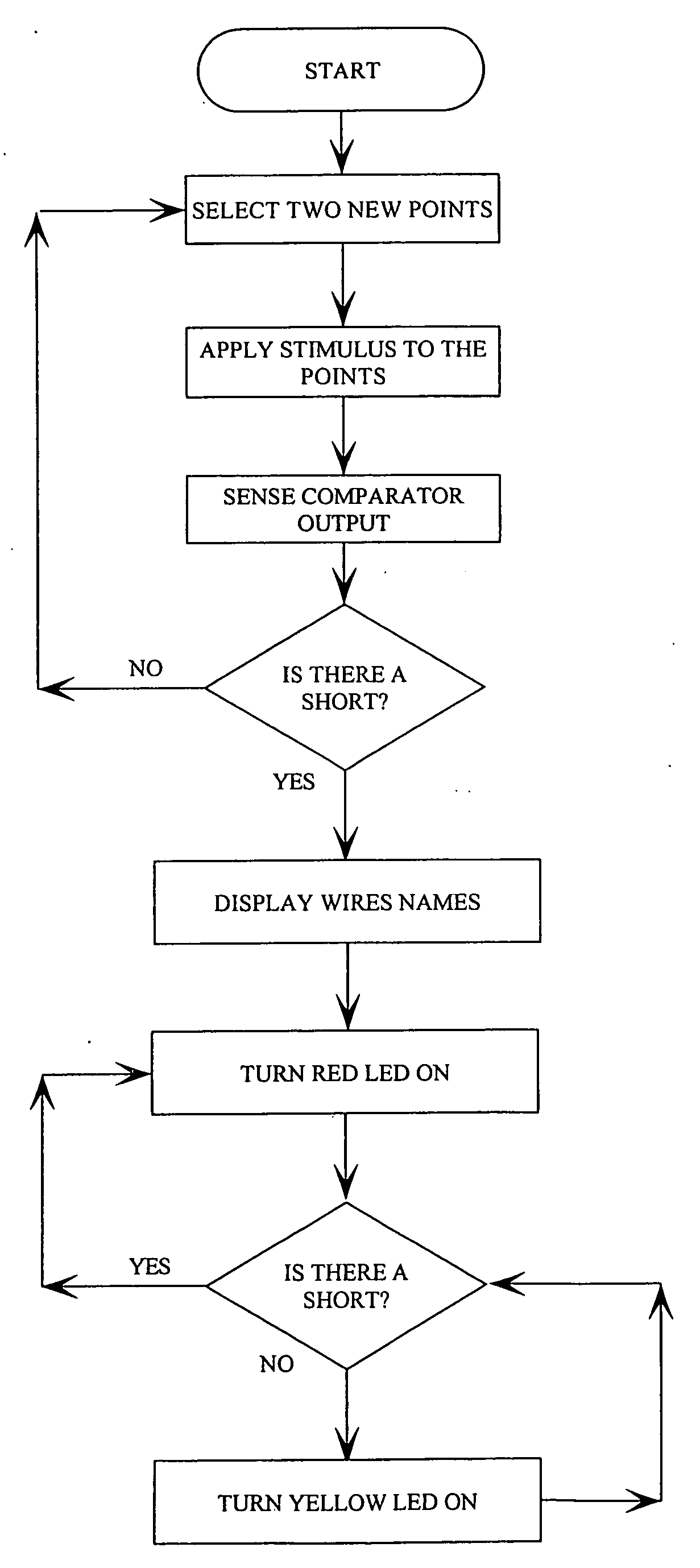
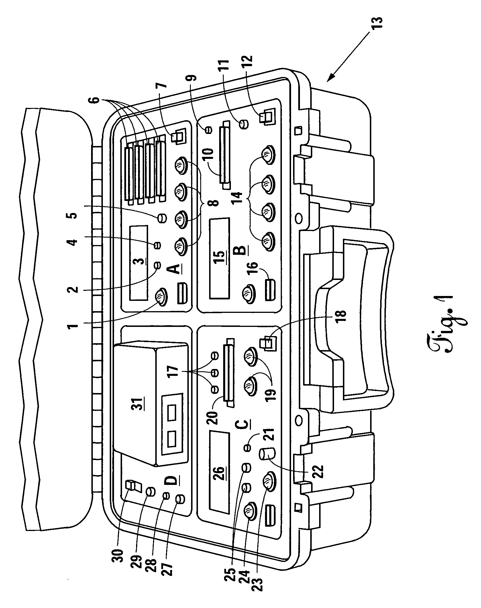
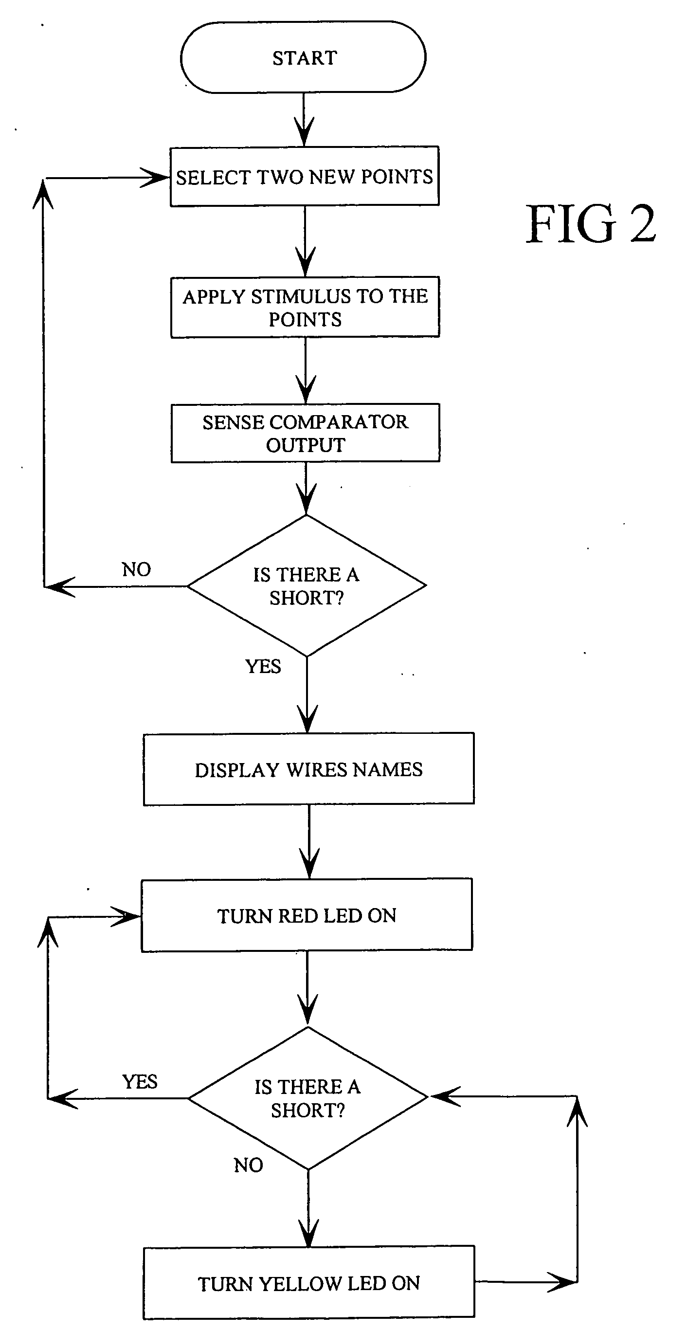
[0036]FIG. 1 illustrates the preferred embodiment of the present invention. The testing unit (13) is divided into four subsystems (A, B, C, D). Subsystem (A) is the “INTERMITTENCE.” It contains the circuitry, the controls and the display. It uses a combination of hardware and software to test and find the location of intermittence in a wire within a wiring harness. The wiring harness connects to Subsystem (A) connectors (6). The power switch (7) provides the external power (27), or the internal battery power. The operator uses four control buttons: LIST, LOOP, INTERMITTENCE, EXIT (8). The LIST control button displays all shorts or opens between the wires. The LOOP control button automatically repeats the test and displays the shorts or opens as they are detected. The INTERMITTENCE control button registers and displays an intermittent short or open. The EXIT button exits the mode of operation. When a control button is pressed for less than two seconds, this Subsystem tests for shorts...


PUM


Abstract

The invention comprises, inter alia, a portable and easy to use tester for troubleshooting and determining the location of wiring intermittence shorts and wiring intermittence opens. The tester can also check the wire ability to carry a load and detect corrosion and bad contacts. Finally, the invention provides a method to apply the characteristics and qualities of a coaxial cable, to a regular, discrete, multi-wire harness. This method will improve the functionality of a conventional Time-Domain Reflectometer (TDR) system that typically can test only two wires at a time, connected to its input. By providing regular wires the characteristics and qualities of a coaxial cable this method will allow the creation of an expansion box that can interface to a conventional TDR system, and increase the number of wires it can test.

Description

REFERENCE TO RELATED APPLICATION [0001] This application claims the benefit U.S. Provisional Application No. 60 / 691,961, filed Jun. 17, 2005, and entitled “Apparatuses and methods for determining and locating wiring intermittence shorts, wiring intermittence opens, the ability of wires to carry a load and determining the distance to shorted or broken wires within a multi strands wire harness, by providing the individual discrete wires within the harness the characteristics and qualities of a coaxial cable.”BACKGROUND OF THE INVENTION [0002] 1. Field of the Invention [0003] The present invention relates to testing equipment for electrical wiring. More specifically, the invention relates to an apparatus and method for testing a wiring harness for intermittent shorts and breaks (opens), and the ability of the wires therein to carry a desired amount of current. [0004] 2. Background of the Invention [0005] There are few effective systems for troubleshooting wiring harnesses. Most such sy...

Claims


Application Information

Patent Timeline
Patent Type & Authority Applications(United States)
IPC IPC(8): G01R31/00G01R31/04
CPCG01R31/021G01R31/11G01R31/024G01R31/58
Inventor KRIGEL, HENRICK YOUVAL
Owner KRIGEL HENRICK YOUVAL
Why Eureka
Try Eureka