Compact optical time domain reflectometer having enhanced accuracy

a time domain reflectometer and compact technology, applied in the direction of optical apparatus testing, instruments, structural/machine measurement, etc., can solve the problems of limited sampling speed of a/d converters, low time accuracy of such ordinary delay elements as used in the arrangement shown in fig. 9, and achieve high accuracy

Inactive Publication Date: 2003-07-15
ANRITSU CORP
View PDF3 Cites 25 Cited by
  • Summary
  • Abstract
  • Description
  • Claims
  • Application Information

AI Technical Summary

Problems solved by technology

However, there is a limitation to the sampling speed of the A / D converter 14 and, in order to maintain the accuracy of the data higher, a problem arises from the fact that it is not preferable to increase the sampling speed up to its limit.
However, the time accuracy of such ordinary delay element as used in the arrangement shown in FIG. 9 is very low and it currently has an accuracy limit of several nanoseconds and, in order to obtain more time resolution, it is necessary to use a cable's delay function.
Incidentally, the delay element using the cable is structurally difficult to manufacture as a smaller unit.
Further, the system using the switching of such delay elements as set out above requires a greater number of elements as the time resolution is enhanced, so that a resultant apparatus becomes bulkier.

Method used


Image

  • Compact optical time domain reflectometer having enhanced accuracy
  • Compact optical time domain reflectometer having enhanced accuracy
  • Compact optical time domain reflectometer having enhanced accuracy

Examples


first embodiment

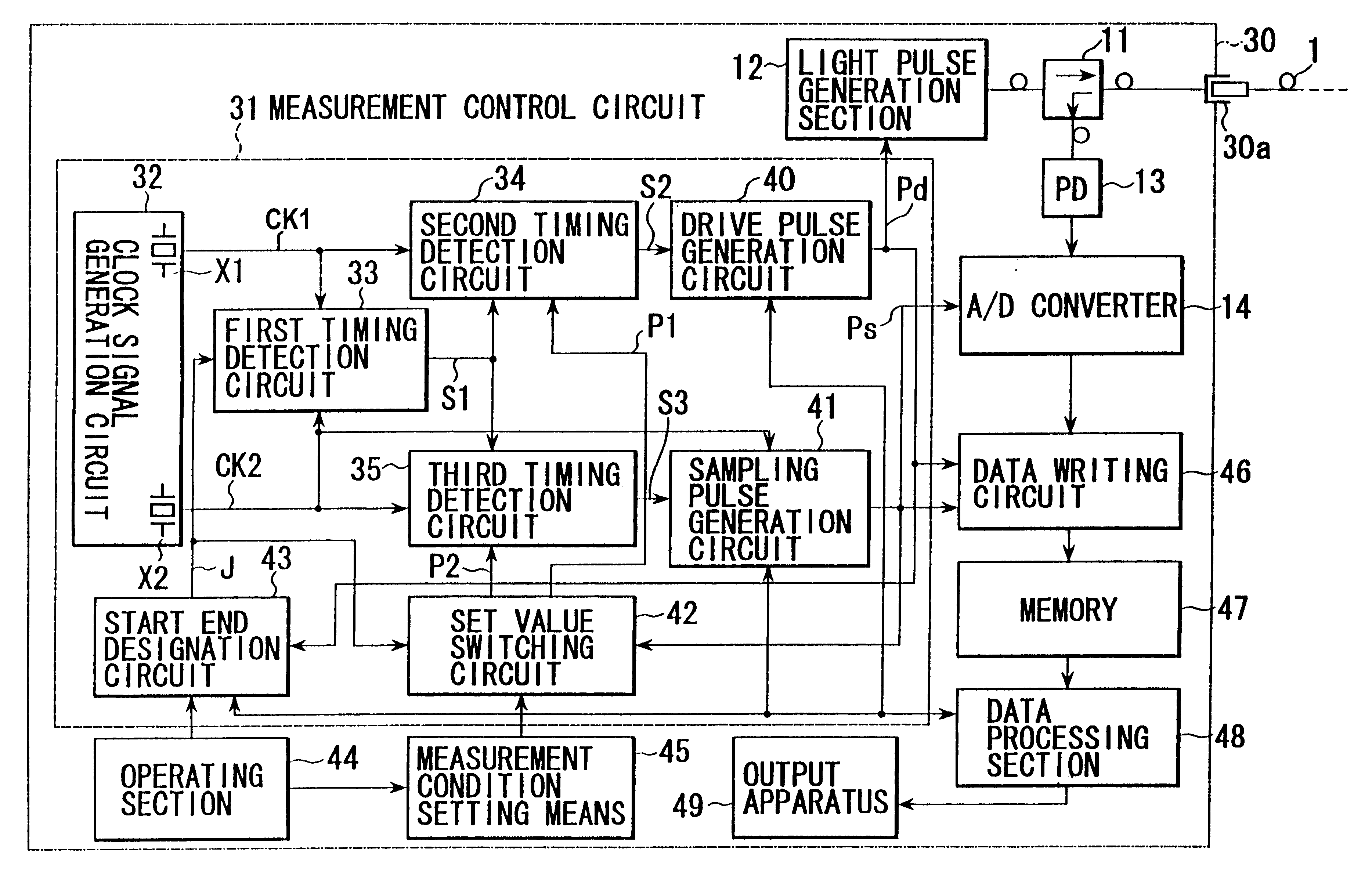
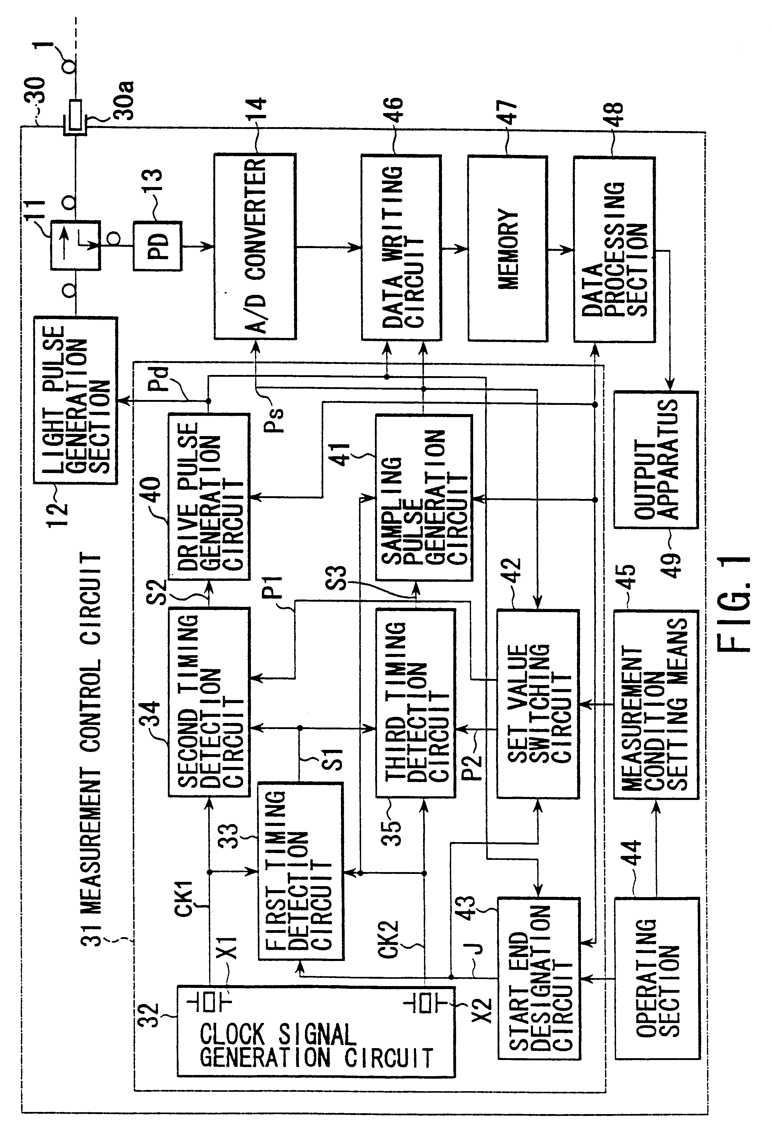
FIG. 1 shows an arrangement of an OTDR 30 according to a first embodiment of the present invention.

In FIG. 1, a directional coupler 11, light pulse generation section 12, light receiving unit 13 and A / D converter 14 have the same structure as that of the conventional OTDR 10 and their explanation is omitted with the same reference numerals employed to designate parts or elements corresponding to those of the conventional OTDR 10.

In the OTDR 30, a light pulse generation section 12 which receives a drive pulse Pd exits a light pulse and this light pulse is incident through a directional coupler 11 into an optical fiber line path 1 connected to a connection terminal 30a.

In the OTDR 30, the light returned back from the optical fiber line path 1 is received by a light receiving unit 13 via the directional coupler 13 and an A / D converter receiving a sampling pulse Ps samples a receiving signal of the light receiving unit 13 to allow it to a digital value.

This OTDR 30 samples the receiving...

second embodiment

The arrangement of the second embodiment is the same as that of the first embodiment shown in FIG. 1.

And, in the second embodiment, from the period difference of two clock signals a delay is given to a timing for starting the sampling of the above-mentioned returned light signal.

That is, in order to make an adjustment on the axis of abscissa (distance) in a display screen of the OTDR 30, it is necessary to make an adjustment between the exit timing of a light (LD) pulse from a light pulse generation section 12 and the timing of sampling returned light (signal) from an optical fiber line path 1 to be measured.

In order to make this adjustment, a delay circuit is required to make a delay time .DELTA.d from the exit timing of the LD pulse to the timing of actually starting the sampling of the light signal accurately (to a time accuracy smaller than the time corresponding to the resolution of the OTDR 30) variable, as shown in FIGS. 5A, 5B and 5C, over a wider range (a time difference re...


PUM

PropertyMeasurementUnit
voltageaaaaaaaaaa
frequencyaaaaaaaaaa
frequencyaaaaaaaaaa

Abstract

A light branching section applies a light pulse emitted in synchronism with a drive pulse (DP), to an optical fiber line path, and receives the light returning from the line path. An A / D converter performs equivalent sampling on the optical signal contained in the returning light, in synchronism with the sampling pulse (SP) of period T0. A measuring control circuit (MCC) generates DP a number (M) of times. The circuit generates N number of SPs every time it outputs DP. It outputs the SPs, at a time delayed by DELTAT that corresponds to 1 / M of the period T0. A clock signal generation circuit outputs to the MCC a first clock signal of a period T1 and a second clock signal of a period T2 different by DELTAt from the period T1. The MCC imparts a delay DELTAT to the SPs, on the basis of the DELTAt.

Description

The present invention relates to an optical time domain reflectometer (hereinafter referred to as an OTDR) and, in particular, to an OTDR for inputting a light pulse into an optical fiber line path and finding an intensity variation of returned light from the optical fiber line path with respect to a time in which the OTDR adopts a technique for achieving an enhanced distance accuracy.In the case where the test of a communication system using an optical fiber line path is carried out, use is made of an OTDR 10 having a structure as shown in FIG. 7.That is, this OTDR 10 is so configured as to input a light pulse from a light pulse generation section 12 through a directional couper 11 to an optical fiber line path 1 as a to-be-tested object connected to a connection terminal 10a, receive the light which is returned back from the optical fiber line path 1 at a light receiving unit 13 via-the directional coupler 11, and, while sampling the receiving signal by an analog / digital (A / D) con...

Claims


Application Information

Patent Timeline
Patent Type & Authority Patents(United States)
IPC IPC(8): G01M11/00
CPCG01M11/3145
Inventor MAKITA, SATOSHI
Owner ANRITSU CORP
Why Eureka
Try Eureka