
Bi-directional multi-pulsewidth optical time-domain reflectometer

a reflectometer and time-domain technology, applied in the field of optical reflectometric methods and systems, can solve the problems of characterization of splice loss, limited ability to characterize short fiber sections, and closely spaced events, and all the above-mentioned multiple-pulsewidth approaches are limited to single-ended measurements, so as to improve the resolution of events.

Active Publication Date: 2014-07-17
EXFO
View PDF4 Cites 22 Cited by
  • Summary
  • Abstract
  • Description
  • Claims
  • Application Information

AI Technical Summary

Benefits of technology

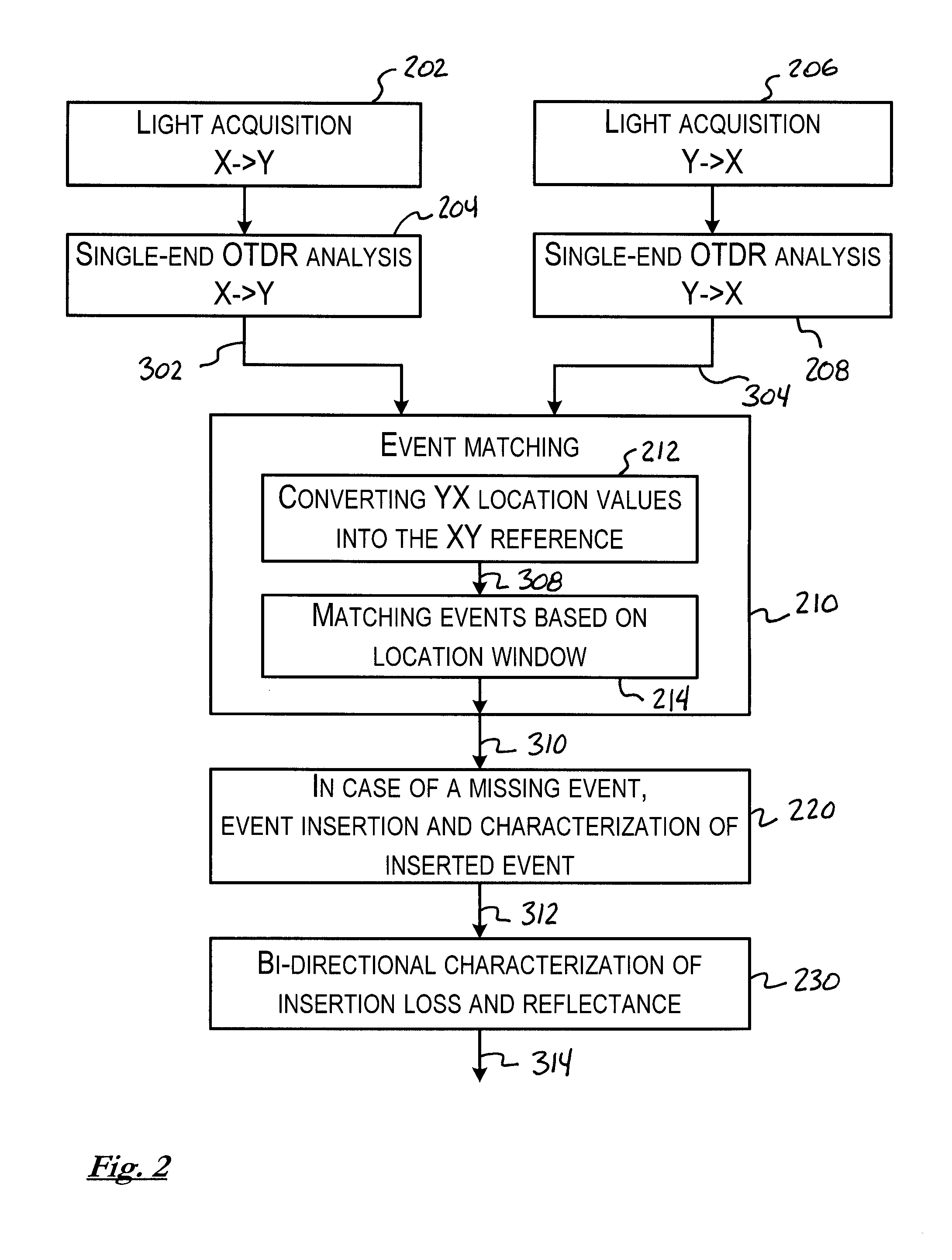
The patent describes a method and system for characterizing optical links using a bi-directional Optical Time-Domain Reflectometric (OTDR) analysis. This method and system benefit from both multi-pulsewidth acquisitions and bi-directional analysis. By identifying events along the fiber link using single-end multi-pulsewidth acquisitions and correlating them together, the system can provide improved resolution for events located closer to both ends of the link. This combination of multi-pulsewidth acquisitions and bi-directional analysis allows for better characterization of splice loss without compromising the resolution. The higher resolution in proximity of both extremities of the optical link allows for better characterization of closely spaced events, which prevents application of reliable pass / fail criteria on those events. The method and system can also allow for better characterization of an event when it is not discernible in both forward- and backward-direction acquisitions.

Problems solved by technology

However, the use of a long pulse brings certain limitations in the ability to characterize short fiber sections, as well as closely spaced events.
However, all the above-mentioned multiple-pulsewidth approaches are limited to single-ended measurements.
A problem with single-end OTDR measurements is the characterization of splice loss in cases where the link under test includes multiple fiber types.
As a consequence, MFD mismatch between spliced fibers may cause an apparent “gain” or a drop in the backscattered light of OTDR measurements, which is not related to the real loss at the point of concatenation (e.g. at a fiber splice).
An OTDR measurement performed from the opposite end on the same fiber splice would conversely result in an overestimation of the splice loss.
For this reason, single-end OTDR measurements do not allow for proper characterization of such events.
The spatial resolution of the OTDR measurement is therefore limited by this constraint and high-resolution bi-directional OTDR measurements are not possible.

Method used


Image

  • Bi-directional multi-pulsewidth optical time-domain reflectometer
  • Bi-directional multi-pulsewidth optical time-domain reflectometer
  • Bi-directional multi-pulsewidth optical time-domain reflectometer

Examples


Embodiment Construction

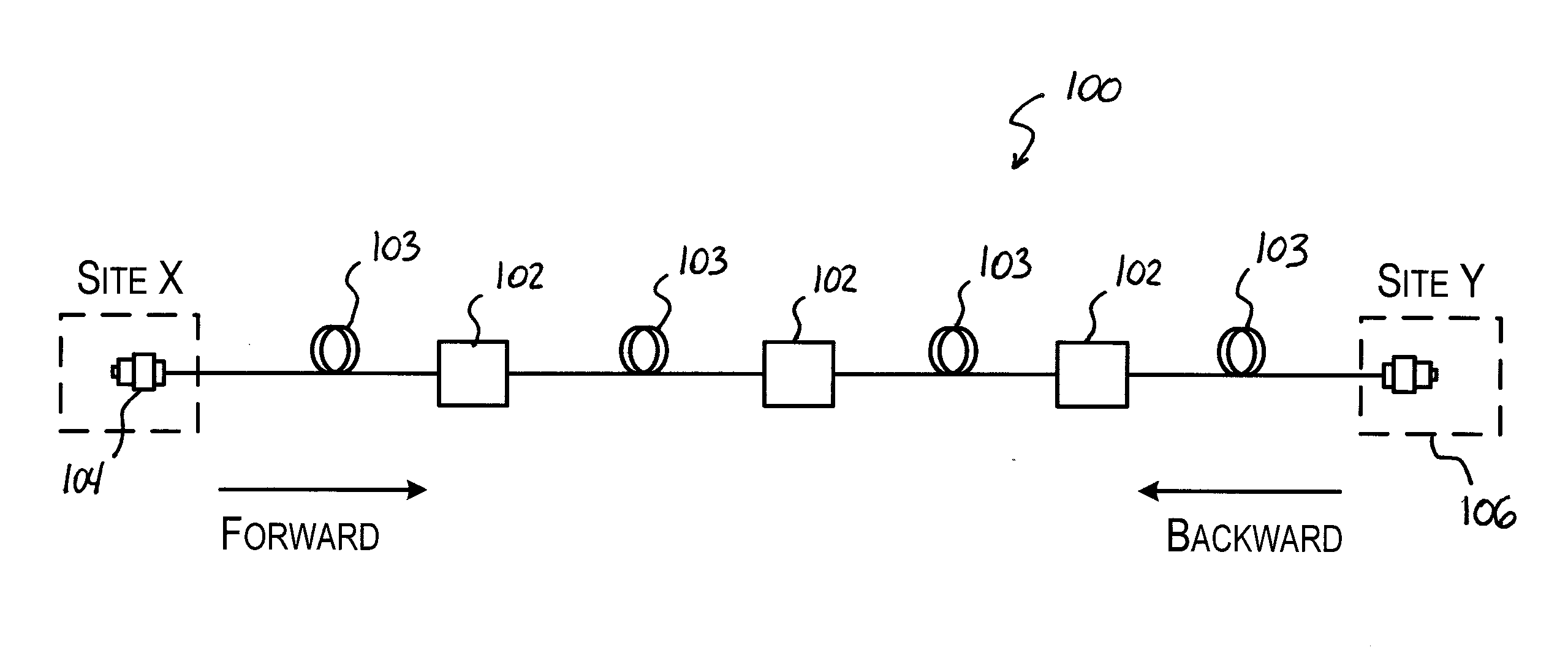
[0047]Referring to FIG. 1, there are provided bi-directional multi-pulsewidth Optical Time-Domain Reflectometric (OTDR) methods and systems for characterizing an optical fiber link 100 between physical sites X and Y using a bi-directional OTDR analysis.

[0048]OTDR is a diagnostic technique for optical fiber networks where a light pulse is launched in an optical fiber link and the returning light, arising from backscattering and reflections along the fiber link, is detected and analyzed. Various events 102 along the fiber link 100, which delimit optical fiber segments 103, can be detected and characterized through a proper analysis of the returning light in the time domain. In order to perform a bi-directional characterization, single-end OTDR measurements should be made from both forward and backward directions on the fiber link 100. To perform the forward-direction characterization, an OTDR system (not shown) is connected to the first end 104 of the fiber link 100 (located at site X...


PUM


Abstract

There is provided a bi-directional optical reflectometric method for characterizing an optical fiber link. The method comprises: performing a plurality of forward-direction light acquisitions from one end of the optical fiber link and performing a plurality of backward-direction light acquisitions from the opposite end, wherein each light acquisition is performed by propagating at least one test light signal corresponding to given spatial resolution and detecting corresponding return light so as to obtain a reflectometric trace representing backscattered and reflected light as a function of a distance on the optical fiber link, and wherein said plurality of forward-direction light acquisitions and said plurality of backward-direction light acquisitions are each performed with mutually different spatial resolutions; and deriving a value of at least one parameter characterizing an event along said optical fiber link at least using a forward-direction light acquisition and a backward-direction light acquisition performed with mutually different spatial resolutions.

Description

CROSS-REFERENCE TO RELATED APPLICATIONS[0001]This application claims priority under 35USC§119(e) of U.S. provisional patent application 61 / 752,554 filed Jan. 15, 2013, the specification of which is hereby incorporated by reference.TECHNICAL FIELD[0002]The invention relates to the field of optical reflectometric methods and systems, and more specifically to bi-directional Optical Time-Domain Reflectometric (OTDR) methods and systems used to characterize optical fiber links.BACKGROUND OF THE ART[0003]Optical reflectometric methods are widely employed for characterization of optical fiber links. Among these methods, the most commonly used approach is Optical Time-Domain Reflectometry (OTDR—also used to refer to the corresponding device), a diagnostic technique where light pulses are launched in an optical fiber link and the returning light, arising from backscattering and reflections along the fiber link, is detected and analyzed. Various “events” along the fiber link can be detected a...

Claims


Application Information

Patent Timeline
Patent Type & Authority Applications(United States)
IPC IPC(8): G01M11/00
CPCG01M11/3109G01M11/3145G01M11/39G01M11/3118
Inventor L'HEUREUX, MARIOLECLERC, MICHELTHOMASSIN, ERICPERRON, STEPHANE
Owner EXFO
Learn More