Optical fiber characterization measurement systems and methods

Active Publication Date: 2019-09-10
CIENA
View PDF32 Cites 20 Cited by
  • Summary
  • Abstract
  • Description
  • Claims
  • Application Information

AI Technical Summary

Benefits of technology

[0011]In another embodiment, an optical node in an optical line system configured to characterize an optical fiber one or more components configured to perform functions during operation of the optical node, wherein the one or more components are configured to perform one or more measurements to characterize the optical fiber, wherein the one or more components perform functions during operation of the optical node and are reconfigured to perform the one or measurements independent of the functions; and an optical modem which is configured for communication over the optical fiber based on the one or more measurements. The one or more components each can include any of an Optical Service Channel (OSC), an Optical Time Domain Reflectometer (OTDR), and an optical amplifier. The launch power into the optical fiber for the optical modem can be set based on the one or more measurements.
[0012]The one or more components can include an Optical Time Domain Reflectometer (OTDR), and the one or more measurements can include an OTDR measurement with a configurable reflection element configured to provide a clear reference point at an end of the optical fiber, wherein a length of the optical fiber is determined from the OTDR measurement based on the clear reference point. The configurable reflection element can include a 1×N Microelectromechanical systems (MEMS) switch configured to share the OTDR component with a plurality of optical fibers.
[0013]The one or more components can include i) an optical amplifier, and ii) devices configured to provide an optical wavelength outside of amplification bandwidth of the optical amplifier, and the one or more measurements can include a measurement of power P1 of the optical wavelength at a downstream node from the optical node with the optical amplifier disabled; a measurement of power P2 of the o

Problems solved by technology

The out-of-service measurements are time-consuming, costly, and error-prone (e.g., loading measured data into planning tools, spreadsheets, etc.).
Also, the out-of-service measurements may not reflect future conditions when an optical system is in-service.
Using an OTDR trace, it is generally difficult or impossible to unambiguously identify the end of the fiber as it may not be a clear signature in the OTDR trace.
RTD measurements have limited accuracy (+/−5%) because of timing jitter of the OSC packets.
There is no known commercial equipment to perform t

Method used


Image

  • Optical fiber characterization measurement systems and methods
  • Optical fiber characterization measurement systems and methods
  • Optical fiber characterization measurement systems and methods

Examples


Embodiment Construction

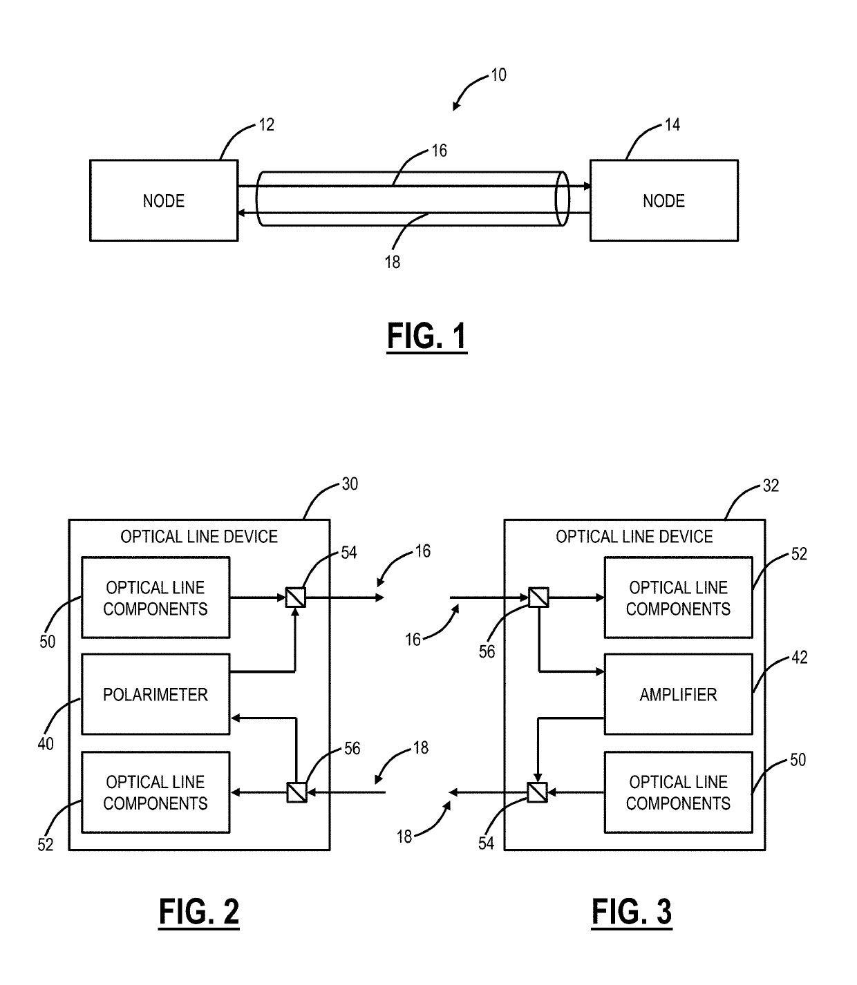
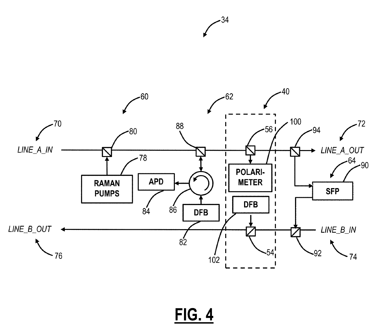
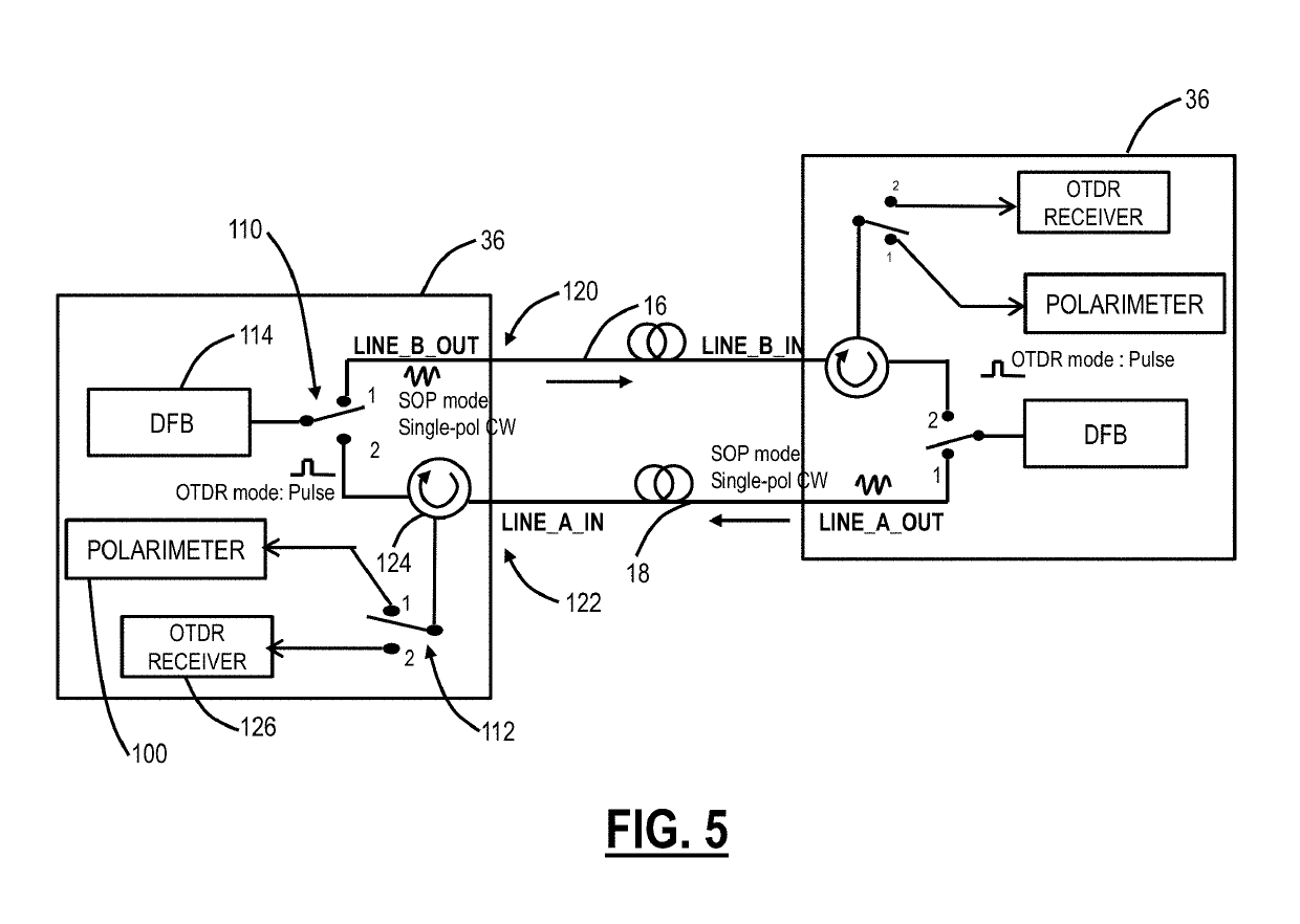
[0032]In various embodiments, the present disclosure relates to optical fiber characterization measurement systems and methods such as to determine fiber span length, Stimulated Raman Scattering (SRS) measurements, dispersion measurements, etc. for use in optical networking systems. The optical fiber characterization measurement systems and methods enable in-service measurements of various optical properties and the associated configuration of an optical line system based thereon, including automatic configuration. With advanced optical systems, it is very desirable to accurately know the fiber span length, nonlinear measurements such as SRS, dispersion measurements, etc. for configuration of various settings including launch power, dispersion compensation filter settings, etc. The conventional approach of estimation sufficed for previous generation systems, but the inaccuracy costs margin which is needed when operating at 100's Gb / s or more and with next-generation optical modems w...


PUM


Abstract

Systems and methods for characterizing an optical fiber performed in part by an optical node in an optical line system include performing one or more measurements to characterize the optical fiber with one or more components at the optical node, wherein the one or more components perform functions during operation of the optical node and are reconfigured to perform the one or measurements independent of the functions; and configuring the optical node for communication over the optical fiber based on the one or more measurements. The one or more components can include any of an Optical Service Channel (OSC), an Optical Time Domain Reflectometer (OTDR), and an optical amplifier. The configuring can include setting a launch power into the optical fiber based on the one or more measurements.

Description

FIELD OF THE DISCLOSURE[0001]The present disclosure generally relates to fiber optic communication systems and methods. More particularly, the present disclosure relates to optical fiber characterization measurement systems and methods such as to determine fiber span length, Stimulated Raman Scattering (SRS) measurements, dispersion measurements, etc. for use in optical networking systems.BACKGROUND OF THE DISCLOSURE[0002]Optical fiber characterization measurements can include, for example, fiber span length, Stimulated Raman Scattering (SRS) measurements, dispersion measurements, loss measurements, etc. The conventional approach to fiber characterization involves out-of-service measurements with test equipment and / or estimates based on calculations (e.g., loss and dispersion determined based on length, fiber type, etc.). The out-of-service measurements are time-consuming, costly, and error-prone (e.g., loading measured data into planning tools, spreadsheets, etc.). Also, the out-of...

Claims


Application Information

Patent Timeline
IPC IPC(8): H04B10/27H04B10/071H04Q11/00H04B10/079
CPCH04Q11/0062H04B10/07955H04B10/0797H04B10/07951H04B10/071H04B10/27H04Q2011/0083G01M11/3127G01M11/3136G01M11/3154G01M11/3163G01M11/319G01M11/39H04B10/077H04B10/075
Inventor ARCHAMBAULT, JEAN-LUCCAO, SONGKIM, NA YOUNG
Owner CIENA
Why Eureka
Try Eureka