
Dual wavelenth optical time domain reflectometer systems and methods embedded in a WDM system

a technology of optical time domain reflectometer and wavelength division multiplexing, which is applied in the field of fiber optic systems and methods, can solve the problems of inability to detect events, inability of uni-directional otdr to distinguish between lossy splices, and inability to integrate with wdm systems or operate in-service with such wdm systems

Active Publication Date: 2017-10-12
CIENA
View PDF0 Cites 22 Cited by
  • Summary
  • Abstract
  • Description
  • Claims
  • Application Information

AI Technical Summary

Benefits of technology

The patent describes a dual wavelength Optical Time Domain Reflectometer (OTDR) system that can be embedded in a network element to monitor traffic-bearing channels in real-time. The system includes two OTDR sources, an OTDR measurement subsystem, and one or more ports for connecting the sources and measurement subsystem to fiber pairs. The system can provide OTDR trace data to an external system and can detect bend loss and splice or connector loss to monitor intrusion on a fiber. The technical effects of this system include improved operational flexibility and improved security in the network.

Problems solved by technology

Thus, conventional OTDRs are not designed for integration with WDM systems or to operate in-service with such WDM systems.
This makes it difficult to detect “events” such as pinched fibers, lossy connectors or splices near the upstream node, as the OTDR trace has less resolution and becomes noisier the further an event is from the OTDR source.
Another issue is that a uni-directional OTDR is in some cases unable to distinguish between a lossy splice and a change in fiber type, as both can generate a similar drop in OTDR signal.
Of course, such conventional implementations do not operate in real time as well as having additional complexity and coordination requirements.

Method used


Image

  • Dual wavelenth optical time domain reflectometer systems and methods embedded in a WDM system
  • Dual wavelenth optical time domain reflectometer systems and methods embedded in a WDM system
  • Dual wavelenth optical time domain reflectometer systems and methods embedded in a WDM system

Examples


Embodiment Construction

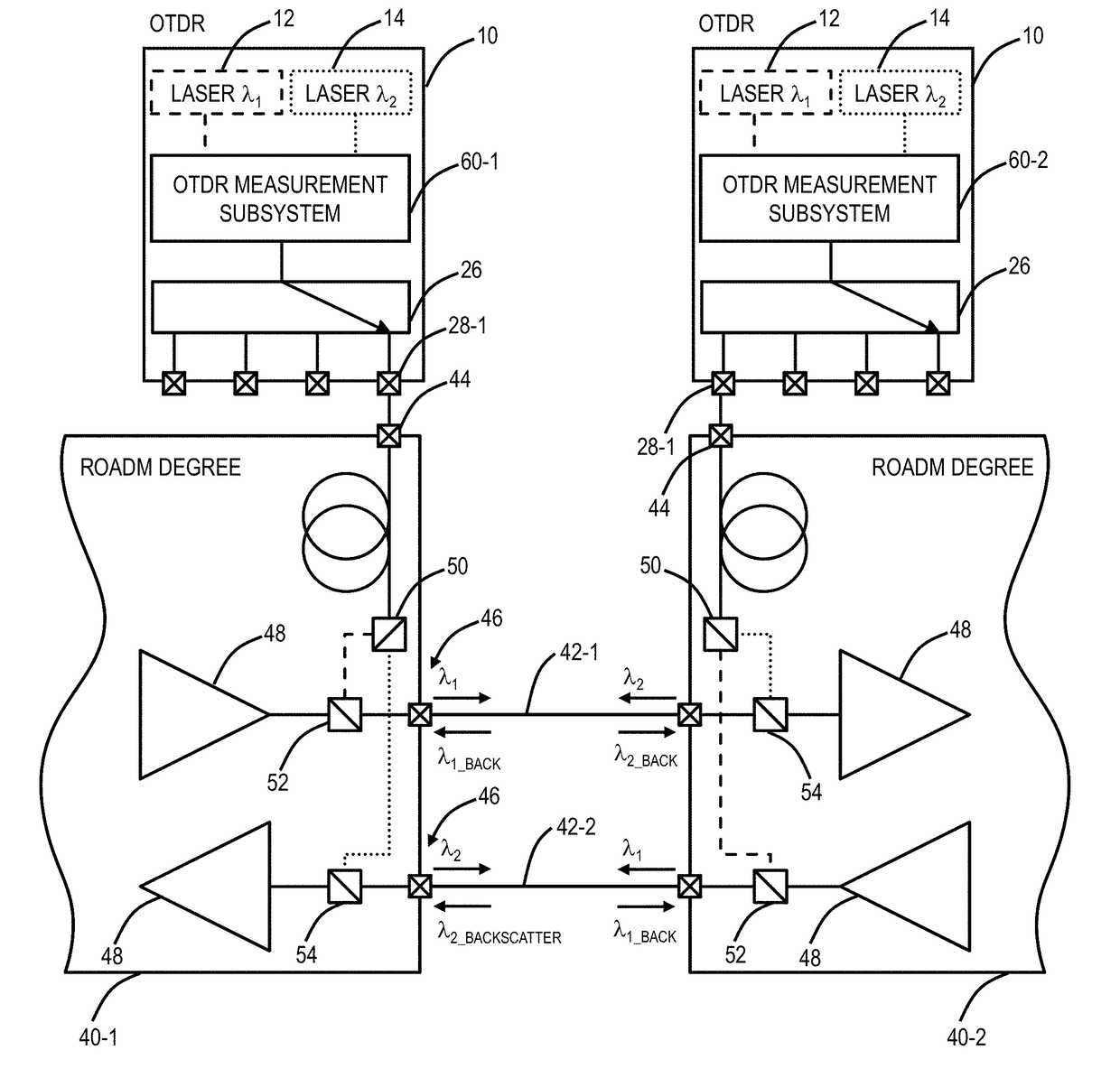
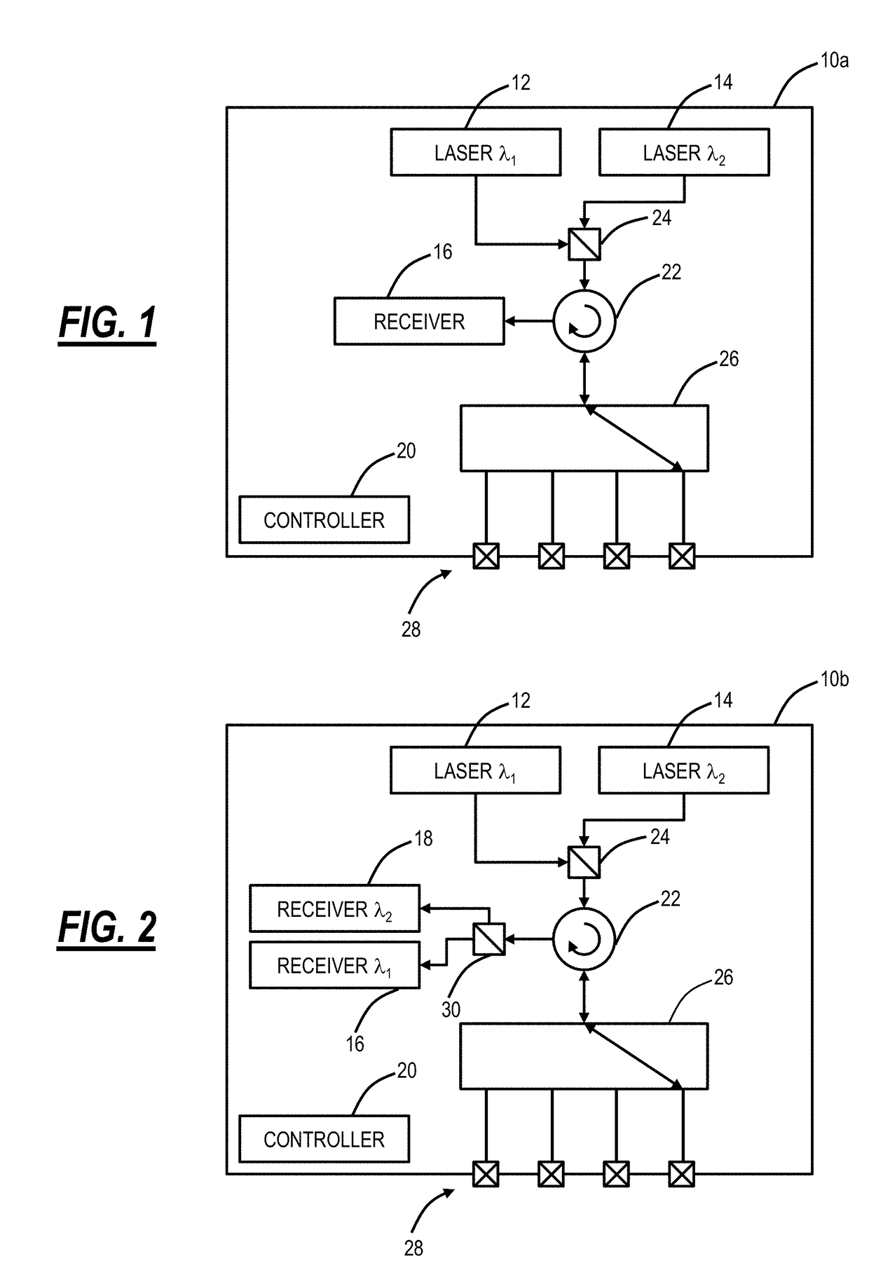
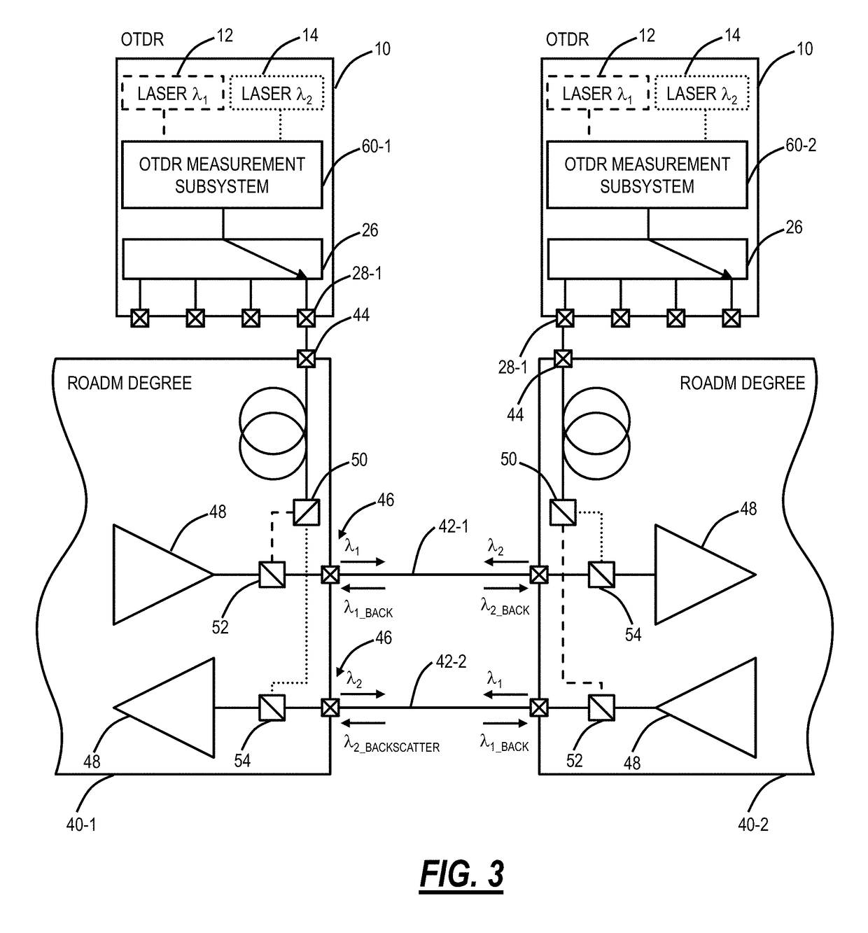
[0017]Again, in various exemplary embodiments, the present disclosure relates to a dual wavelength Optical Time Domain Reflectometer (OTDR) systems and methods embedded in a Wavelength Division Multiplexing (WDM) system. Note, while reference is made to WDM systems, the systems and methods can operate with any type of fiber optic communication systems, such as Dense WDM or the like as well. Variously, the systems and methods include an OTDR measurement system which can be integrated into a WDM system, such as an optical amplifier, optical transceiver, or any other module. The OTDR measurement system is integrated into components of the WDM system at both ends of a fiber span, operating on a fiber under test and providing real-time bi-directional OTDR capability. Thus, the OTDR measurement system can provide simultaneously and independent OTDR monitoring embedded in the WDM system. The OTDR measurement system includes a dual-wavelength design, capable of in-service operation with a p...


PUM


Abstract

A dual wavelength Optical Time Domain Reflectometer (OTDR) system, embedded in a network element, includes a first OTDR source for wavelength λ1; a second OTDR source for wavelength λ2; an OTDR measurement subsystem adapted to measure backscatter signals λ1_BACK, λ2_BACK associated with the wavelength λ1 and the wavelength λ2; and one or more ports connecting the first OTDR source, the second OTDR source, and the OTDR measurement subsystem to one or more fiber pairs; wherein wavelength λ1 and wavelength λ2 are each outside of one or more signal bands with traffic-bearing channels, thereby enabling operation in-service with the traffic-bearing channels.

Description

FIELD OF THE DISCLOSURE[0001]The present disclosure generally relates to fiber optic systems and methods. More particularly, the present disclosure relates to a dual wavelength Optical Time Domain Reflectometer (OTDR) systems and methods embedded in a Wavelength Division Multiplexing (WDM) system.BACKGROUND OF THE DISCLOSURE[0002]Conventionally, OTDRs inject a series of optical pulses into a fiber under test and extract, from the same end of the fiber, light that is scattered (i.e., Rayleigh backscatter) or reflected back from points along the fiber. Results from OTDRs are used for estimating the fiber's length, overall attenuation, and discontinuities along the fiber. Traditionally, OTDRs are external devices relative to optical network elements (e.g., WDM systems) which operate while the fiber under test is dark (i.e., no working traffic from the optical network elements). Thus, conventional OTDRs are not designed for integration with WDM systems or to operate in-service with such...

Claims


Application Information

Patent Timeline
Patent Type & Authority Applications(United States)
IPC IPC(8): H04B10/071H04J14/02H04Q11/00H04B10/077
CPCH04B10/071H04B10/0775H04Q2011/0083H04Q11/0062H04J14/0212
Inventor ARCHAMBAULT, JEAN-LUCBOERTJES, DAVID W.
Owner CIENA
Learn More