
Method and radar system for determining the directional angle of radar objects

Inactive Publication Date: 2005-02-15
ROBERT BOSCH GMBH
View PDF12 Cites 53 Cited by
  • Summary
  • Abstract
  • Description
  • Claims
  • Application Information

AI Technical Summary

Benefits of technology

An object of the present invention is to provide a method for determining directional angles which is more reliable with respect to the interference effects that occur when working with real radar objects.
When the results obtained for various measuring frequencies are inconsistent to the point where a clear directional angle cannot be determined, one at least receives the information that a reliable determination of the directional angle is not possible at the particular moment, thereby lessening the danger of erroneous determinations being made with respect to the directional angle.
However, even given a proper object assignment, interference effects can result in more or less substantial deviations in the directional angles, which are obtained for the same measuring frequency, from the various spectra. For that reason, for the consistency check, it is not only the results obtained for the various measuring frequencies that are compared to one another, but the results obtained from various spectra, i.e., from various ramps of the frequency modulation, as well. When, at a given measuring frequency, the results obtained from the various spectra deviate from one another, then this indicates that the result for this special measuring frequency is falsified by interference effects. In determining the most plausible directional angle, the result obtained for this measuring result is then weighted less heavily or completely excluded from the evaluation. Conversely, the plausibility of an obtained directional angle is rated to be all the higher, the more frequently this directional angle is confirmed by the evaluation of other spectra. Altogether, therefore, the accuracy and reliability can be considerably enhanced in this way.
The greater the number of beams of the multibeam radar is, the greater the angular resolution and the measuring accuracy generally become. However, as the number of beams increases, the evaluation on the basis of the reference patterns also becomes more complex.

Problems solved by technology

However, real (tangible) radar objects, in particular large objects such as trucks, usually have a plurality of centers of reflection, whose radar echoes are superposed in the various receiving elements and interfere with one another.
This can degrade the accuracy and reliability of the angular determination.

Method used


Image

  • Method and radar system for determining the directional angle of radar objects
  • Method and radar system for determining the directional angle of radar objects
  • Method and radar system for determining the directional angle of radar objects

Examples


Embodiment Construction

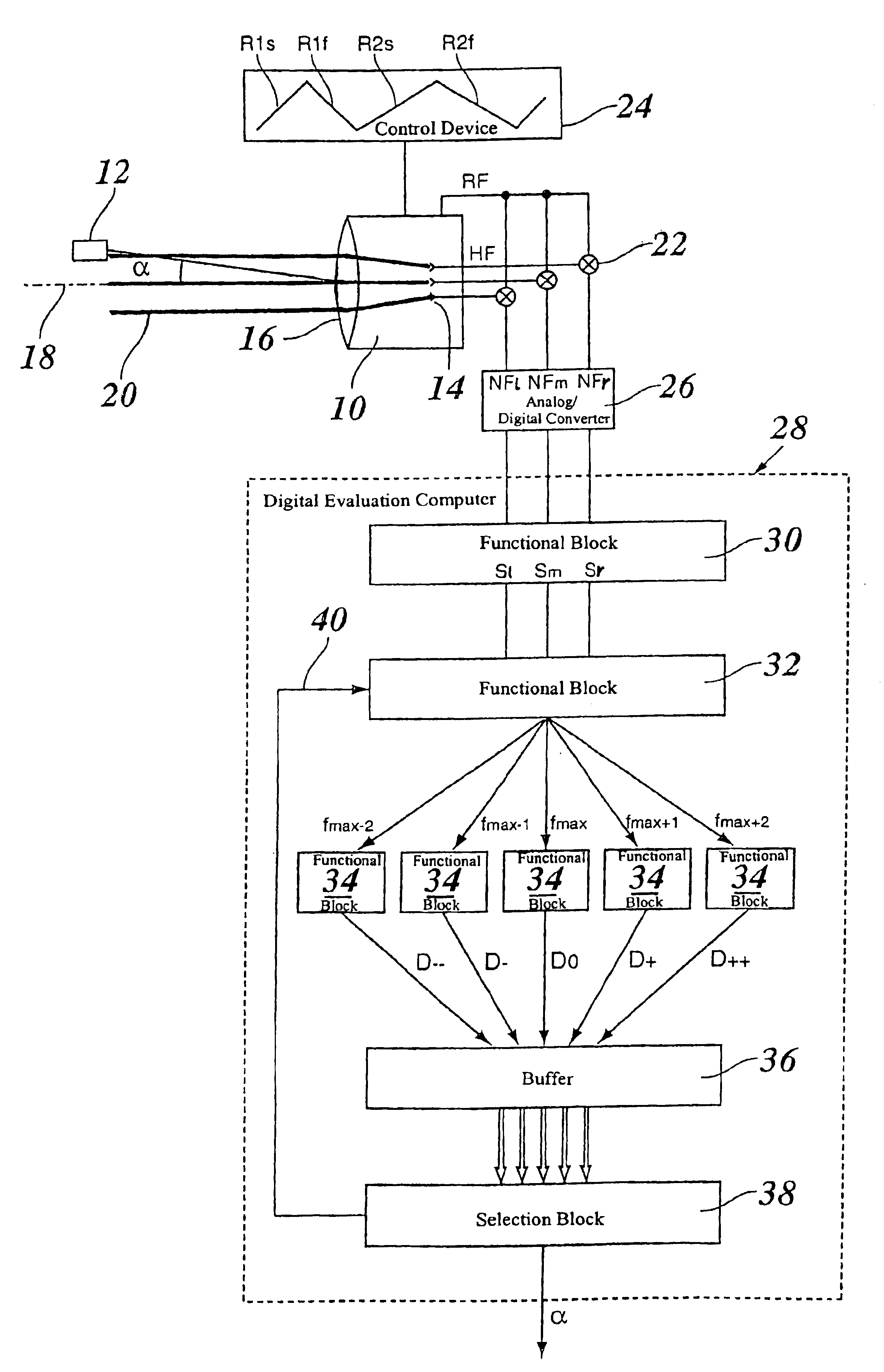
FIG. 1 schematically depicts a radar sensor of a multibeam radar 10, which is installed on the front-end section of a motor vehicle and is used for finding the position of radar objects 12 located ahead of the vehicle. Multibeam radar 10, has three transmitting and receiving elements 14, referred to in the following, in short, as receiving elements, of which one is situated on optical axis 18 defined by an optical system 16 of the radar sensor, while the two others are configured so as to be laterally offset from the optical axis. In this manner, three measuring beams 20 are produced, which are emitted at different angles with respect to the optical axis. In practice, measuring beams 20 shown in the drawing only as lines, have the form of radar lobes which extend over relatively large, overlapping angular ranges. The lines in FIG. 1 indicate the direction of each intensity maximum of these radar lobes.

Radar object 12 is generally hit by all three radar lobes, and, for each measuring...


PUM


Abstract

A method for determining the directional angle of radar objects using a multibeam radar, including the steps of:(a) recording the frequency spectra of the radar echoes for a plurality of beams;(b) seeking a measuring frequency near a frequency maximum assigned to the radar object; and(c) comparing the phases and / or amplitudes of the radar echoes at the measuring frequency with reference patterns known for various directional angles,steps (b) and (c) being executed repeatedly, each time for different measuring frequencies, and the directional angles obtained for the various measuring frequencies being checked for consistency.

Description

FIELD OF THE INVENTIONThe present invention is directed to a method for determining the directional angle of radar objects using a multibeam radar, including the steps of:(a) recording the frequency spectra of the radar echoes for a plurality of beams;(b) seeking a measuring frequency near a frequency maximum assigned to the radar object; and(c) comparing the phases and / or amplitudes of the radar echoes at the measuring frequency with reference patterns known for various directional angles.BACKGROUND INFORMATIONA method is known from German Patent Application No. 195 43 813. It is used in a motor vehicle to determine the positions of radar objects, for example of vehicles driving ahead, using a static multibeam radar, so that then, within the framework of an adaptive cruise control (ACC), the velocity of one's own vehicle is adapted to the velocity of a vehicle driving ahead, and the distance to the vehicle driving ahead can be regulated to a suitable value. The positions of the rad...

Claims


Application Information

Patent Timeline
IPC IPC(8): G01S13/00G01S13/48G01S13/42G01S13/34G01S13/58
CPCG01S13/48G01S13/424G01S13/345G01S13/584
Inventor EDER, SONJABUDISCAK, BENOIT
Owner ROBERT BOSCH GMBH
Learn More