CAS bone reference and less invasive installation method thereof

a bone reference and less invasive technology, applied in the field of bone reference, can solve the problems of significant additional patient trauma and post-operative pain, significant invasiveness to the patient, and the surgical use may not permit the obstructed space required, so as to reduce the amount of soft tissue damage and not cause significant damag

Inactive Publication Date: 2005-02-15
ORTHOSOFT ULC
View PDF15 Cites 104 Cited by
  • Summary
  • Abstract
  • Description
  • Claims
  • Application Information

AI Technical Summary

Benefits of technology

It is a further object of the present invention to provide a CAS bone reference member that reduces the amount of soft tissue damage caused during its installation on a bone element.
Therefore, in accordance with the present invention, there is provided a method for monitoring position and movement of a bone element using an image guided surgical system, comprising the steps of: providing a bone reference assembly comprising a toothed bone anchor member and a trackable member, the trackable member comprising a detectable element adapted to be located and tracked in three dimensional space by the image guided surgical system, thereby defining position and movement of the trackable member; inserting a protective guide member through soft tissue covering the bone element using a proximal end adapted for gradual separation of the soft tissue so as not to cause significant damage thereto, such that the proximal end is substantially adjacent the bone element, the protective guide member being sized to receive at least the toothed bone anchor member therein; using the protective guide member to guide the toothed bone anchor member into direct engagement with the bone element; engaging the toothed bone anchor member to

Problems solved by technology

However, installation of traditional bone reference members, which are identifiable by the CAS system and are fixed to each bone element, can often be significantly invasive to the patient.
Any unnecessary invasiveness can result in significant additional patient trauma and post-operative pain.
Also, some surgical uses may not permit the obstructed space required for the relatively wider stance that the pined-type bone reference membe

Method used


Image

  • CAS bone reference and less invasive installation method thereof
  • CAS bone reference and less invasive installation method thereof
  • CAS bone reference and less invasive installation method thereof

Examples


Embodiment Construction

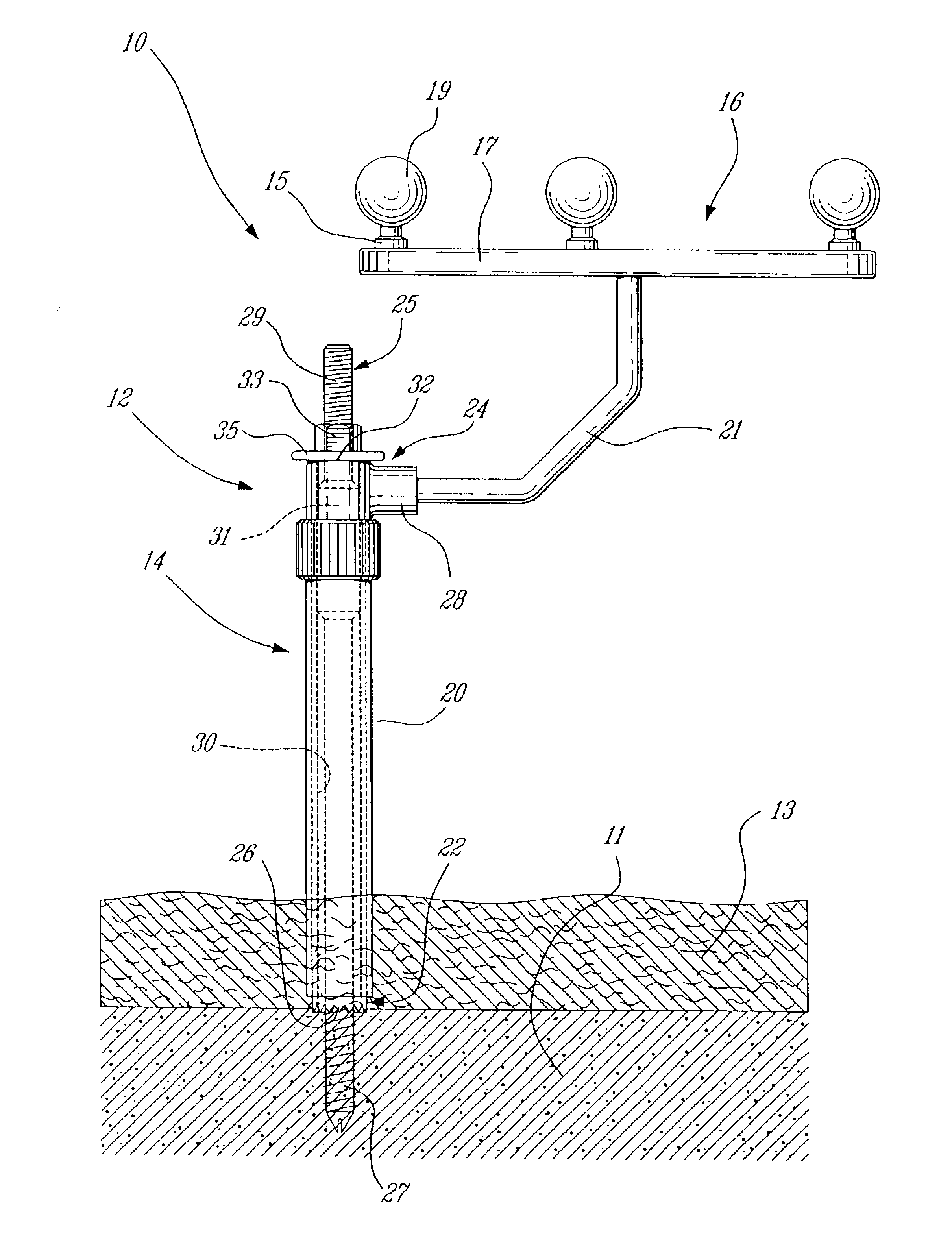
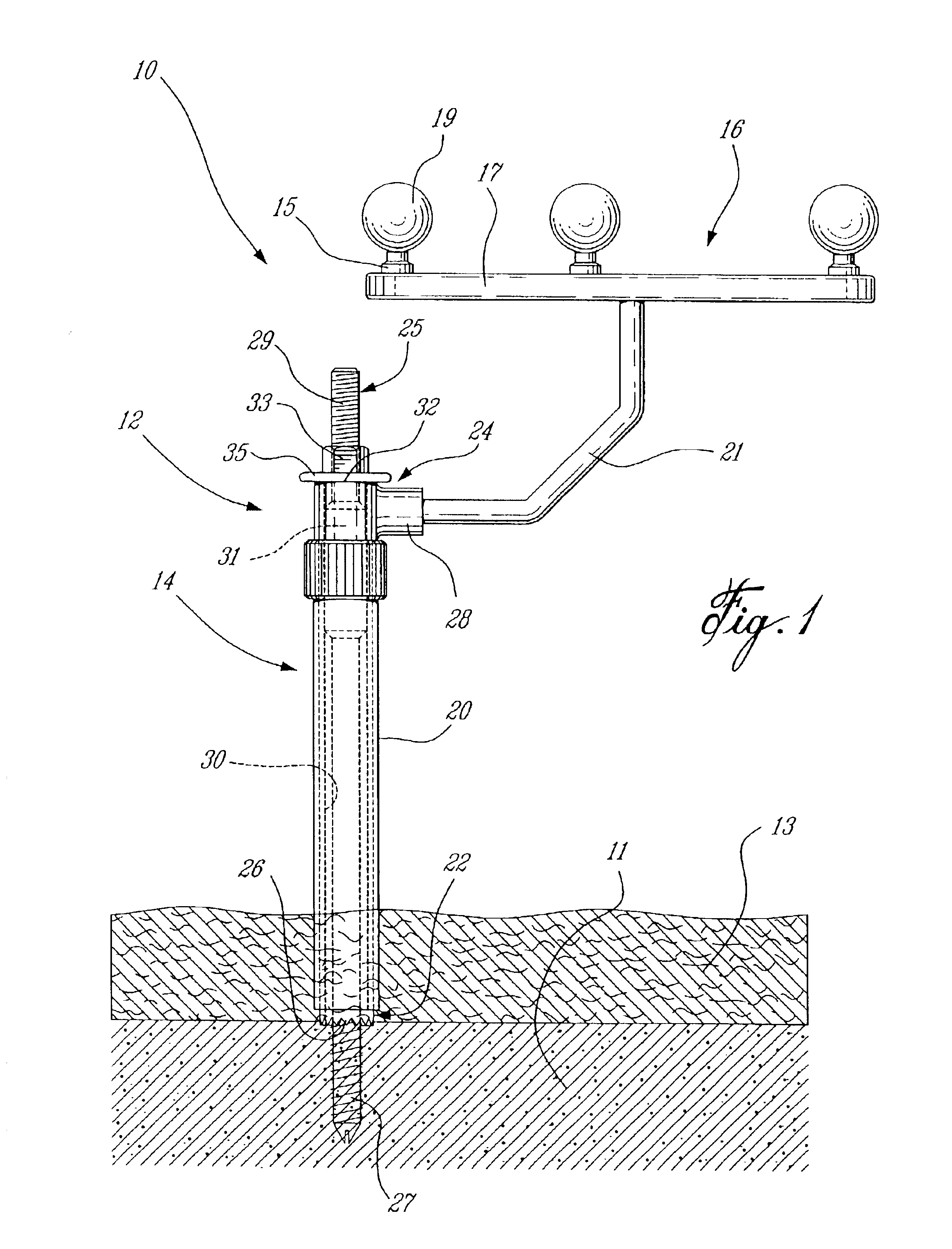
Referring to FIG. 1, the CAS body reference assembly 10 comprises generally a main bone reference element 12, a protective outer sleeve 14, a trackable member 16, and a cortical screw 25.

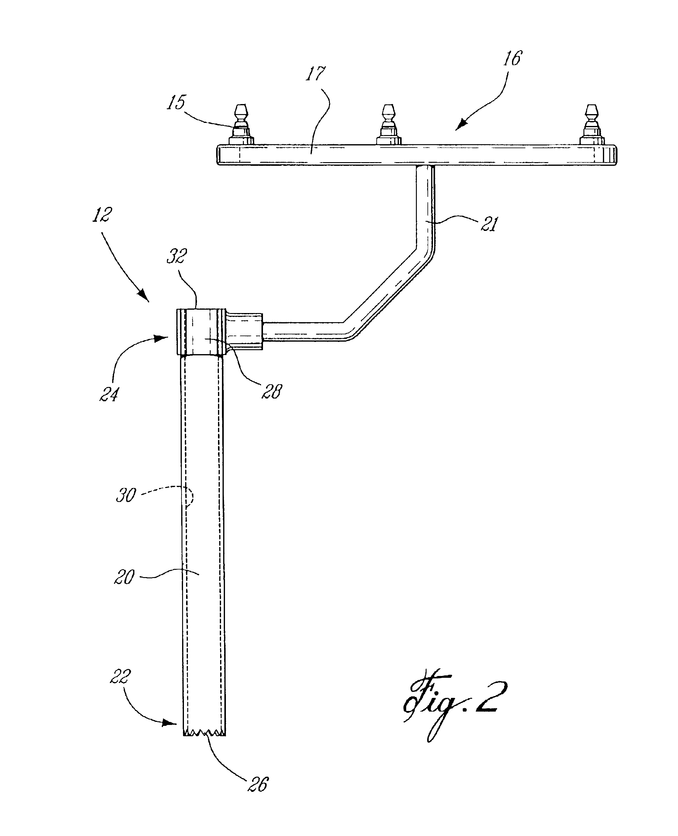
The bone reference element 12, seen alone in FIG. 2, comprises principally an elongated tubular body 20 having a proximal end 22 and a distal end 24. The proximal end 22 is preferably the same diameter as the tubular body 20, and includes a plurality of proximally extending teeth 26 thereon. The teeth 26 are adapted for gripping engagement with the surface of a bone element 11 to which the bone reference assembly 10 is to be anchored. The term teeth as used herein comprises generally any substantially sharp or serrated anchoring element, adapted for piercing engagement of the bone element. These teeth preferably comprise substantially jagged projecting elements, disposed repeatedly substantially about the full circumference of the proximal end 22 of the bone reference element 12. However, they could...


PUM


Abstract

A surgical bone reference assembly is communicable with an image guided surgical system such that position and movement of a bone element are monitorable. A bone anchor member comprises a trackable member and teeth engageable with the bone element. The trackable member comprises a detectable element adapted to be located and tracked in three dimensional space by the image guided surgical system, thereby defining position and movement of the trackable member. A protective guide member is used with the bone anchor member such that the bone anchor member is insertable through soft tissue covering the bone element without causing significant damage thereto. The bone anchor member is engageable with the bone element, such that the teeth are forced into engagement with the bone element and the bone anchor member is fastenable to the bone element in a fixed relation thereto.

Description

TECHNICAL FIELDThe present invention relates generally to a bone reference for use in conjunction with a computer assisted surgery (CAS) system. More particularly, the present invention relates to a trackable bone reference member engageable with a separately installed outer sleeve that limits invasiveness of the installation of the bone reference member.BACKGROUND OF THE INVENTIONCAS systems capable of real time location and tracking of a plurality of discrete objects in a surgical field are now becoming increasingly well known. A variety of systems are employed, however all require the patient bone elements to be identified and registered to pre-operatively taken anatomical scans or intra-operatively taken images of the same bone elements. In order for the relevant bone elements to be located and tracked by the CAS system, trackable reference members must be fastened thereto. These bone reference members will vary depending on the type and specific requirement of the particular CA...

Claims


Application Information

Patent Timeline
IPC IPC(8): A61B19/00A61B17/86A61B17/68A61B17/34
CPCA61B19/54A61B17/3496A61B19/5225A61B2019/5487A61B2019/481A61B2019/5416A61B2019/5483A61B2017/8655A61B90/37A61B90/39A61B2090/08021A61B2090/3916A61B2090/3983A61B2090/3987
Inventor COSSETTE, SEBASTIENJANSEN, HERBERTCHOUINARD, BENOIT
Owner ORTHOSOFT ULC
Why Eureka
Try Eureka