Traction pins for railway cars

a technology for traction pins and railway cars, which is applied in the direction of bogies, railway components, transportation and packaging, etc., can solve the problems of railcar cabs, significant assembly time, labor and expense, and known drawbacks of conventional traction pin assemblies

Inactive Publication Date: 2005-02-22
COLUMBUS STEEL CASTINGS
View PDF15 Cites 1 Cited by
  • Summary
  • Abstract
  • Description
  • Claims
  • Application Information

AI Technical Summary

Benefits of technology

Accordingly, it is an object of the present invention to eliminate the multiple

Problems solved by technology

Known drawbacks exist with respect to the conventional traction pin assemblies.
By way of example, the use of multiple plates to attach the traction pin to the railcar cab add

Method used


Image

  • Traction pins for railway cars
  • Traction pins for railway cars
  • Traction pins for railway cars

Examples


Embodiment Construction

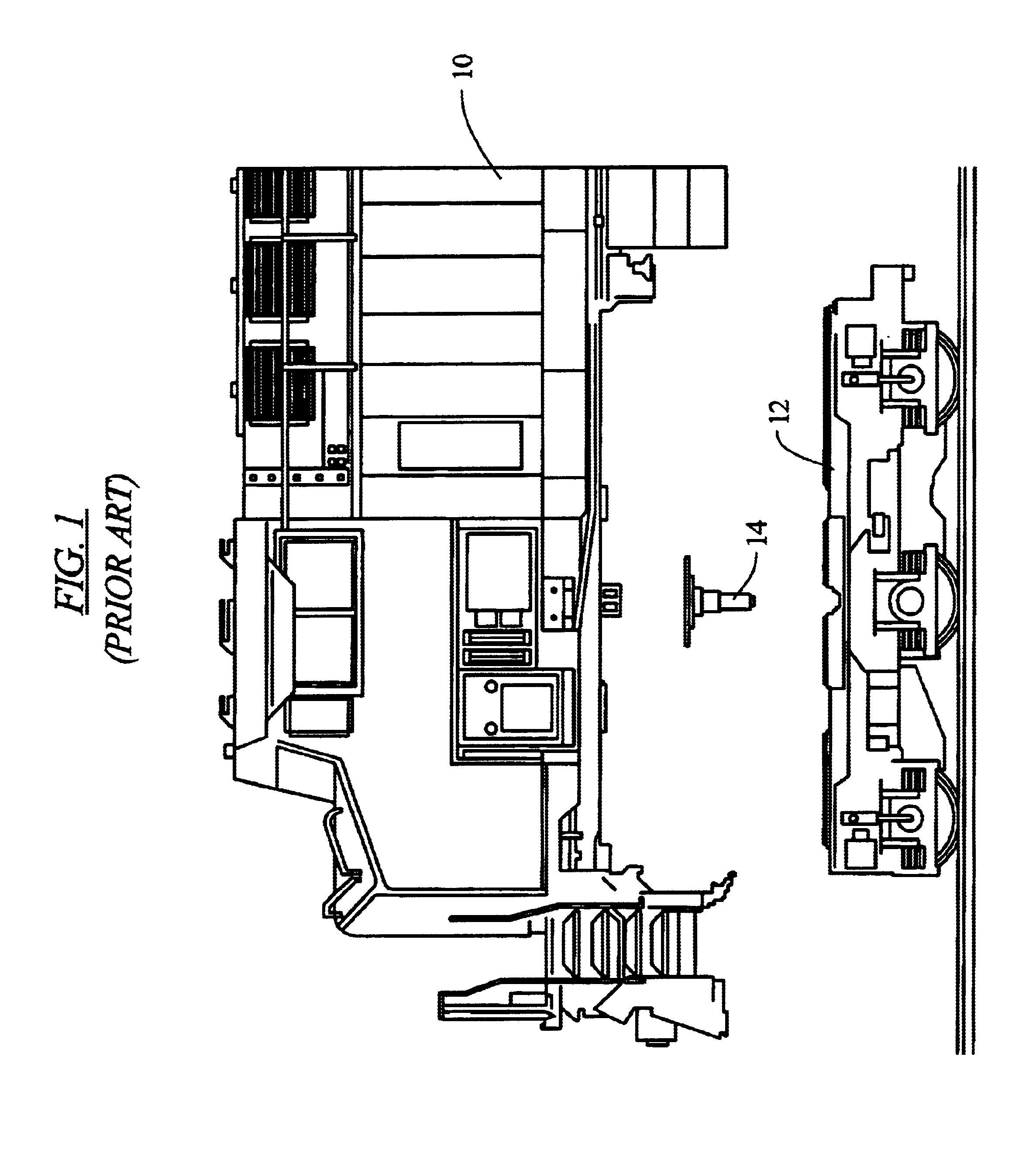
Referring to the figures wherein like numerals indicate like elements, there is shown in FIG. 1 a railcar cab 10 and truck assembly 12. Located between and joining the railcar cab and truck assembly is a traction pin 14. As known by those of skill in the art, the traction pin serves to join the cab and truck assembly and permit rotatable movement of the cab relative to the truck assembly.

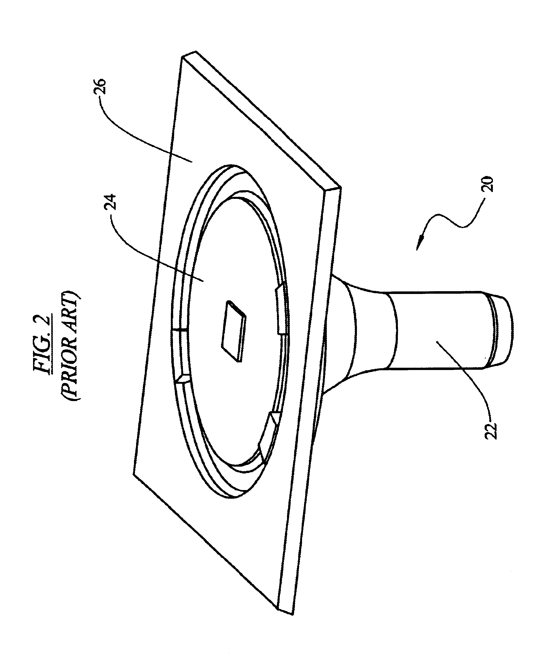
Referring to FIGS. 2-4, there is depicted a prior art traction pin assembly 20 used to join a railcar cab and truck assembly. The prior art traction pin assembly includes a traction pin 22 and multiple plates welded to the traction pin 22. As conventional, the traction pin 22 is welded to a circular steel plate 24 and a square steel plate 26. The plates 24, 26 are, in turn, welded to the underframe of the cab or house assembly of the railcar. The steel plates 24, 26 are typically roll formed by a rolling mill and thus have mechanical properties dependent on the direction of the roll.
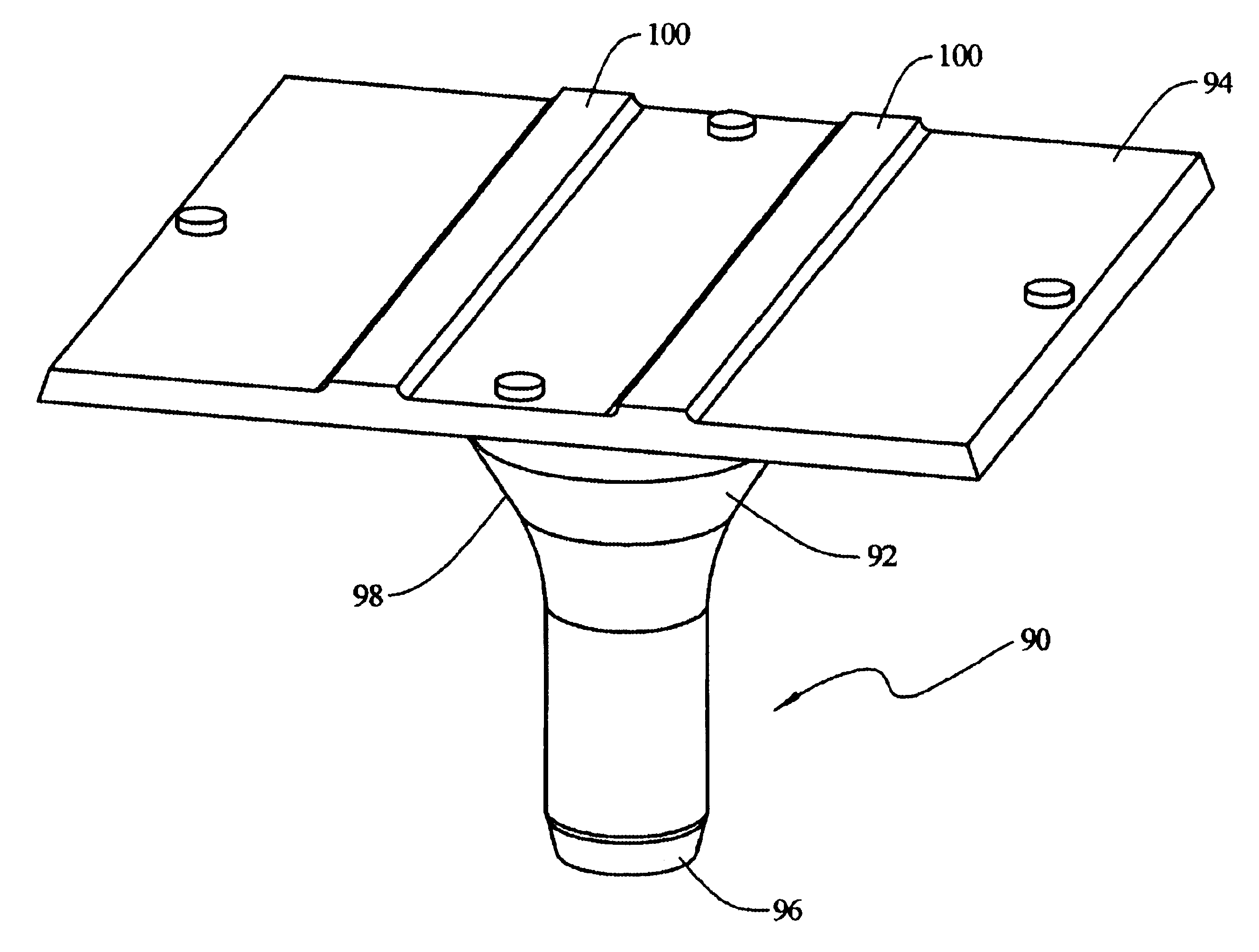
Referring to FIG...


PUM


Abstract

A one-piece, cast traction pin for use with railway cars. The traction pin is used to connect the railcar cab with the railcar truck assembly. The traction pin includes a mounting plate cast integral with the pin, thereby eliminating the use of multiple welded plates. The one-piece cast traction pin is also solid to reduce the potential for stress related failure of the traction pin during normal operation of the railway car.

Description

FIELD OF THE INVENTIONThe present invention is directed generally to traction pins for railway car assemblies. More particularly, the present invention is directed to a cast, one-piece traction pin.BACKGROUND OF THE INVENTIONThe prior art traction pin assembly is a multi-piece component that connects a railcar cab or house assembly to the railcar truck. As conventional, the traction pin assembly is welded to the underside of the railcar cab and engages the railcar truck assembly permitting the truck assembly to turn, or swivel, independently of the cab.As is known in the art, the traction pin assembly includes several components that are welded together and to the railcar cab. These components include a cylindrical pin and multiple mounting plates. The pin is welded to the mounting plates which, in turn, are welded to the underframe of the railcar cab. The mounted traction pin assembly is then received in a mating opening in the railcar truck to complete the joinder of the cab to th...

Claims


Application Information

Patent Timeline
IPC IPC(8): B61F5/02B61F5/16
CPCB61F5/16
Inventor MILLIGAN, BRUCE A.MURPHY, PATRICK M.PINKSTOCK, STEVEN R.
Owner COLUMBUS STEEL CASTINGS
Why Eureka
Try Eureka