
Power working machine with internal combustion engine having spark plug

a technology of internal combustion engine and working machine, which is applied in the direction of sparking plugs, machines/engines, combustion air/fuel air treatment, etc., can solve the problems of increased cost and reduced workability, and achieve the reduction of weight of the entire internal combustion engine, the effect of increasing the maintenance workability of the spark plug and cos

Inactive Publication Date: 2005-02-22
KIORITZ
View PDF6 Cites 10 Cited by
  • Summary
  • Abstract
  • Description
  • Claims
  • Application Information

AI Technical Summary

Benefits of technology

The present invention has been made in consideration of the foregoing problems. Accordingly, it is an object of the present invention to provide a power working machine and a spark plug guard capable of contributing to an increase in maintenance workability of a spark plug, weight reduction of the entire internal combustion engine, and cost reduction.
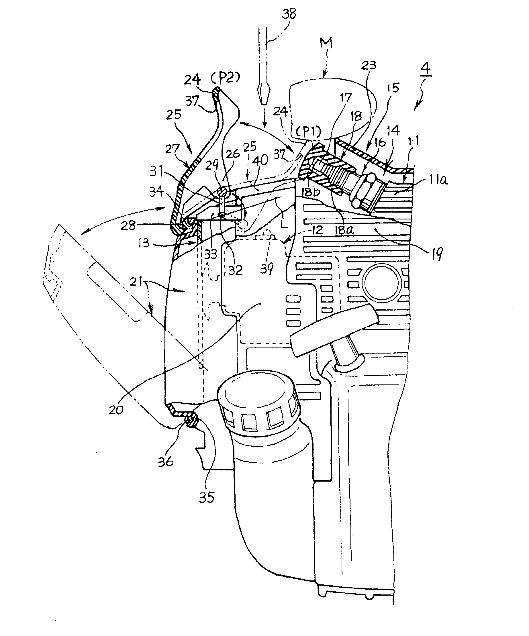
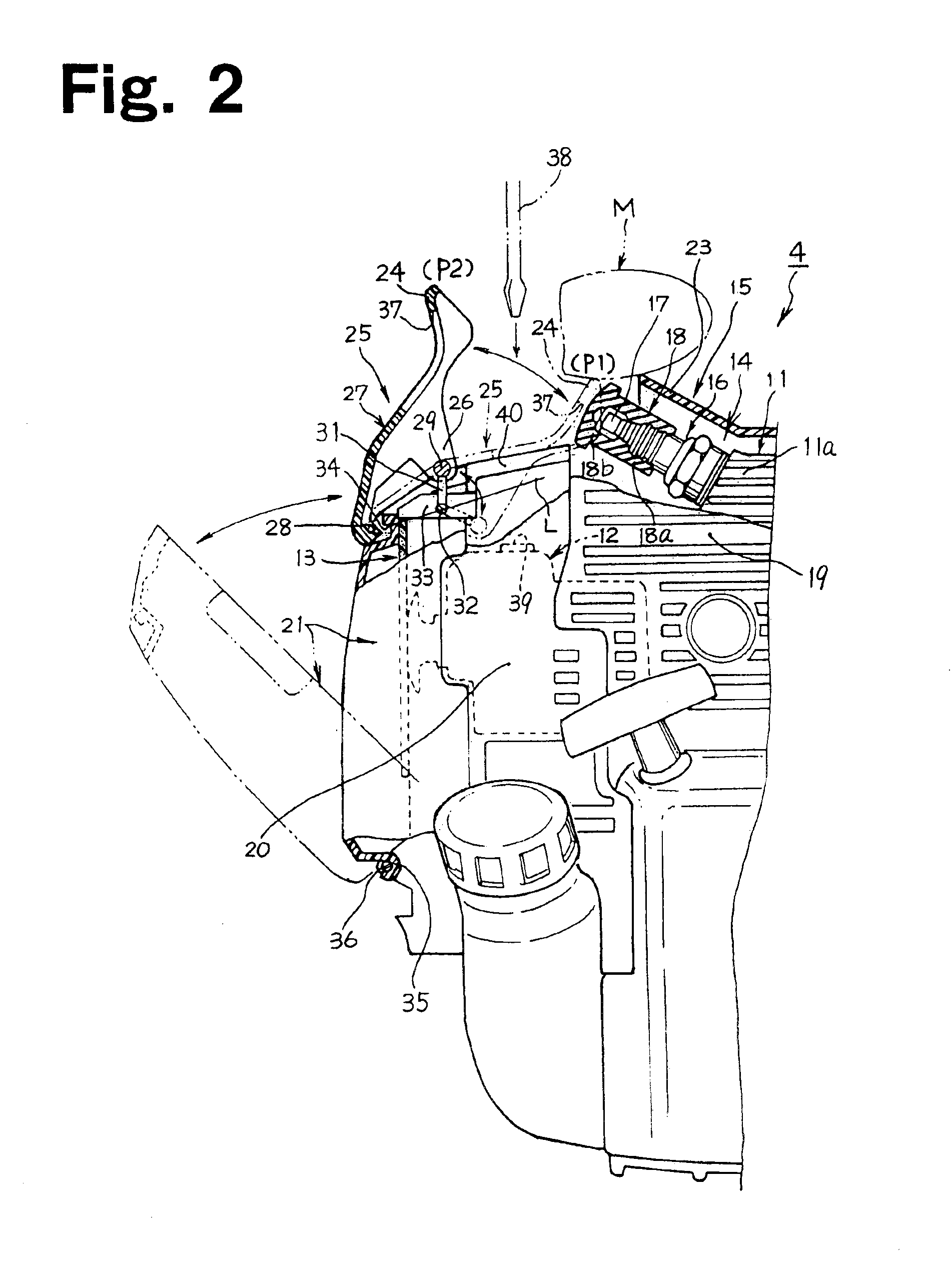
As a preferable embodiment, the finger hole may face a plug cap put on the spark plug in the spark-plug covering position. In this case, the finger hole serves as an air-circulating channel toward the plug cap, providing a cooling effect of the spark plug; thus, it is more preferable.

Problems solved by technology

However, if the spark plug guard is secured to the engine body with screws and so on, troublesome detachment work of the spark plug guard is required during maintenance of the spark plug, thus resulting in a decrease in workability.
Also, if a part designed specifically for protection of the spark plug is mounted to the engine body, the machine increases in weight correspondingly, thus going against the demand for compact and lightweight portable working machines and causing an increase in cost.

Method used


Image

  • Power working machine with internal combustion engine having spark plug
  • Power working machine with internal combustion engine having spark plug
  • Power working machine with internal combustion engine having spark plug

Examples


Embodiment Construction

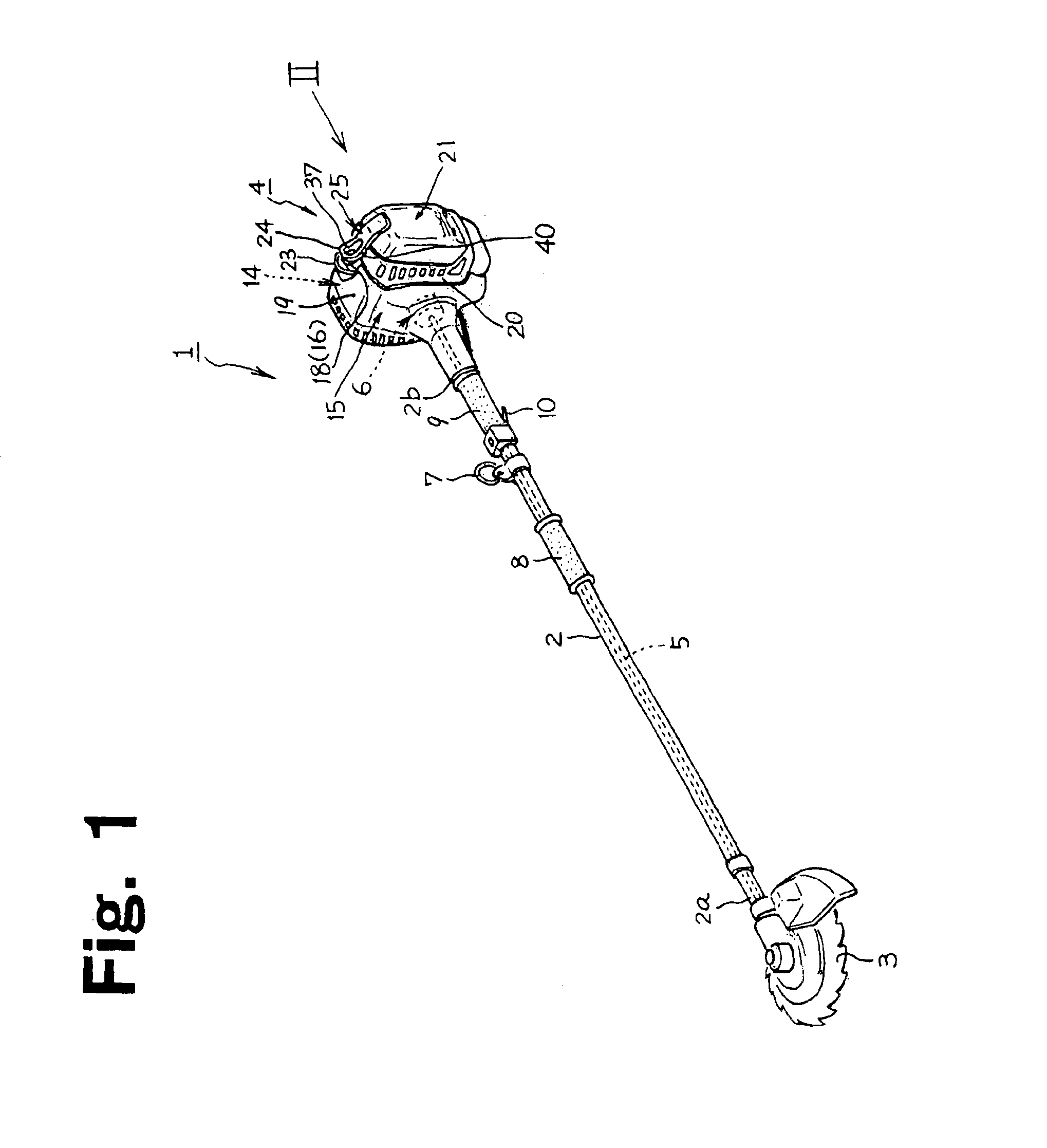
Referring to FIG. 1, a portable brush cutter 1 as a working machine according to an embodiment of the present invention includes a rotary cutting blade 3 as a power working member at the front end 2a of an operating rod 2 extending longitudinally, and includes an internal combustion engine such as a small air-cooled two-stroke cycle gasoline engine 4 at the rear and 2b of the operating rod 2. The driving force by the internal combustion engine 4 is transmitted to the cutting blade 3 via a transmission shaft 5 extending through the operating rod 2. An appropriate type of centrifugal clutch 6 is interposed between the internal combustion engine 4 and the transmission shaft 5. When the rotation speed of the internal combustion engine 4 exceeds a certain value, the rotation driving force is outputted to the cutting blade 3.

The operating rod 2 has a hanging ring 7 near the rear end 2b. An operator can hold the brush cutter 1 on his / her shoulder in a balanced manner by hanging a shoulder ...


PUM


Abstract

A spark plug guard can be switched between a spark-plug covering position to protect a spark plug and a spark-plug opening position. An operator displaces the spark plug guard from the spark-plug covering position to the spark-plug opening position, thereby obtaining a wide working space to perform the maintenance and inspection of the spark plug efficiently. The spark plug guard has a function of fixing a predetermined part in the spark-plug covering position. Consequently, the need for a part fixing member which was conventionally required for fixing the predetermined part to the engine body is eliminated, thus contributing to a decrease in the weight of the whole internal combustion engine and to cost reduction.

Description

BACKGROUND OF THE INVENTION1. Field of the InventionThe present invention relates to a power working machine equipped with an internal combustion engine having a spark plug. The present invention also concerns a spark plug guard for protecting the spark plug.2. Description of the Related ArtSome portable working machines such as brush cutters and hedge trimmers are equipped with an internal combustion engine, such as a small air-cooled two-stroke cycle gasoline engine, as a prime mover for driving a cutting blade (a working member). The internal combustion engine has a spark plug at the head of a cylinder constituting the engine body. The terminal of the spark plug projecting outward from the cylinder head is covered with a detachable plug cap, to which an ignition high-tension lead is connected, for protection.In order to protect the spark plug perfectly, it is preferable to provide a spark plug guard for covering above the plug cap. This is for the purpose of preventing damage to ...

Claims


Application Information

Patent Timeline
Patent Type & Authority Patents(United States)
IPC IPC(8): H01T13/00H01T13/06F02B63/00F02B67/00F02P13/00
CPCH01T13/06
Inventor YAMAMOTO, TAKAYUKI
Owner KIORITZ
Learn More