Flow-actuated trapped-pressure unloader valve

a technology of unloading valve and flow-actuated unloading valve, which is applied in the direction of positive displacement liquid engine, cleaning using liquids, instruments, etc., can solve the problems of adding cost and complexity to the pressure washer, and achieve the effect of reducing cost and complexity, and reducing the number of parts used

Inactive Publication Date: 2005-02-22
BRIGGS & STRATTON LLC
View PDF18 Cites 29 Cited by
  • Summary
  • Abstract
  • Description
  • Claims
  • Application Information

AI Technical Summary

Benefits of technology

Combining the cleaning solution inlet and the unloader valve into a single housing greatly reduces the number of

Problems solved by technology

Chemical injection typically requires a separate appar

Method used


Image

  • Flow-actuated trapped-pressure unloader valve
  • Flow-actuated trapped-pressure unloader valve
  • Flow-actuated trapped-pressure unloader valve

Examples


Embodiment Construction

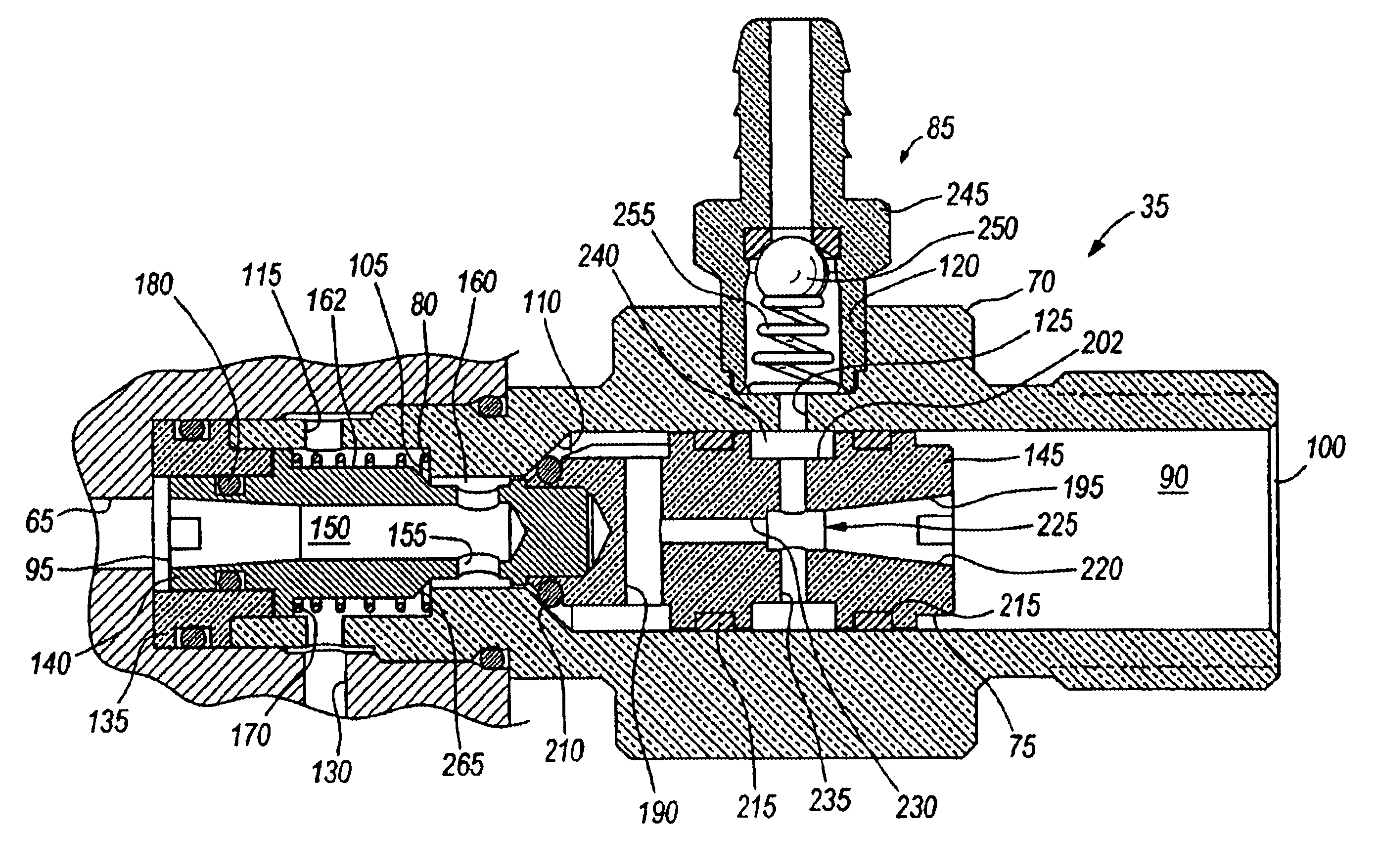
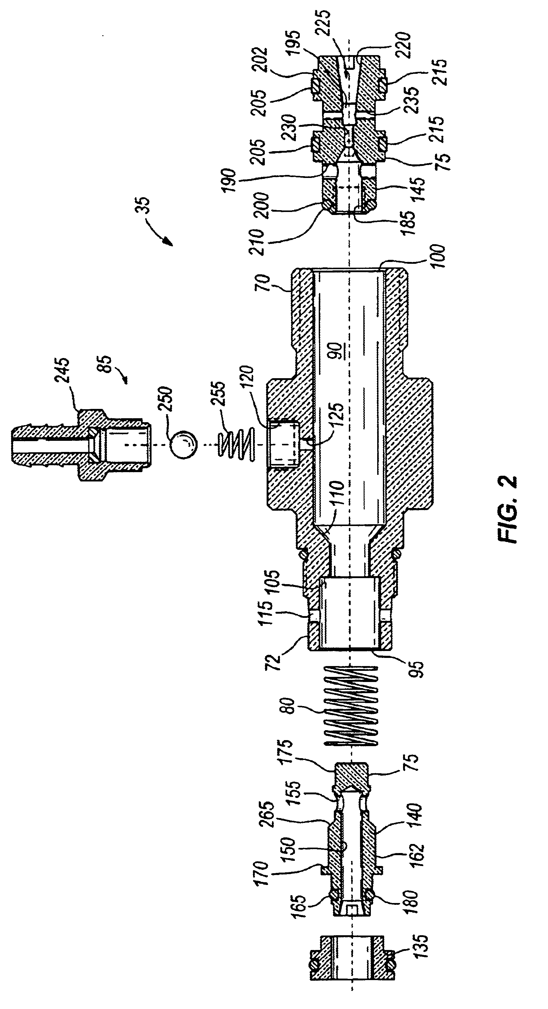
The invention provides an unloader valve including a body that engages the pump housing to receive the high-pressure flow from the pump. The preferred valve body design consists of an inlet, an outlet, a bypass passage and an inlet passage for chemical injection. Within the valve body is a shuttle-valve that defines two primary chambers. These two chambers are in fluid communication with one another through a small port (venturi) in the shuttle-valve. The shuttle-valve is movable between a bypass position and a spray position. The shuttle-valve is biased in the bypass position by a spring on the discharge side of the shuttle valve.

Yet another feature of the invention is the cleaning solution inlet. The cleaning solution inlet allows for the admission of a cleaning solution (e.g., soap, ammonia, detergent, bleach, etc.) into the stream of high-pressure water. Flow exiting the high-pressure outlet first passes through a venturi disposed within the movable shuttle valve. The throat are...


PUM


Abstract

The invention recites an unloader valve operable to direct a flow of fluid. The valve includes a housing having a bypass opening, an inlet opening, an outlet opening and an internal chamber between the inlet opening and the outlet opening. A shuttle valve is disposed within the internal chamber and is movable between a first position wherein the flow of fluid is substantially directed to the bypass opening and a second position wherein the flow of fluid is directed to the outlet opening. The shuttle valve includes an internal flow path having a venturi therein. A biasing member biases the shuttle valve in the first position.

Description

BACKGROUND OF THE INVENTIONThe present invention relates to unloader valves, and particularly to unloader valves used with positive displacement pumps. More particularly, the present invention relates to a flow-actuated unloader valve for a pressure washer system.Pressure washers provide a supply of high-pressure fluid for performing various tasks (e.g., paint and stain removal, drain cleaning, driveway cleaning, etc.). Usually the water is mixed with a cleaning solution such as soap, ammonia solution, bleach, or other chemicals.Pressure washers often include an engine that drives a high-pressure pump to supply the cleaning fluid. A trigger-actuated valve (i.e., spray gun) mounted to the discharge hose from the pump allows the user to remotely control the supply of high-pressure fluid. When the trigger is depressed, cleaning solution is discharged. When the trigger is released, the flow of fluid stops and the pump is disengaged, the engine is turned off, or the high-pressure fluid i...

Claims


Application Information

Patent Timeline
IPC IPC(8): F04B49/02F04B49/035
CPCF04B49/035B08B3/026Y10T137/2587Y10T137/2599Y10T137/2617Y10T137/87249
Inventor DAVIS, GREG
Owner BRIGGS & STRATTON LLC
Why Eureka
Try Eureka