Mining machine and method

a technology of mining machine and cutting machine, which is applied in the direction of cutting machine, surface mining, slitting machine, etc., can solve the problems of reducing production yield, reducing production yield, and varying cut depth across the seam fa

Inactive Publication Date: 2005-02-22
COMMONWEALTH SCI & IND RES ORG
View PDF10 Cites 38 Cited by
  • Summary
  • Abstract
  • Description
  • Claims
  • Application Information

AI Technical Summary

Problems solved by technology

In practice, inaccuracies develop with each subsequent pass due to slippage of a powered roof support advance system which moves the rail, resulting in the depth of cut varying across the face of the seam.
This, in turn, leads to reduced production yields and unnecessary mechanical loading and stresses on the rail and powered roof support advance system.
Thus, because of the slippage of the powered roof support advance system, the inaccuracies accumulate after many passes of the machine.
This, in turn, results in down time in attempting to reposition the rail to correct these accumulated inaccuracies.
None have proved satisfactory as they each require time to set-up, and manual adjustment of some or all of the support powered roof supports.
In addition to the above, a coal seam follows contours and folds in the strata structure and therefore the coal seam is not a predictable shape.
This, in turn, has led to difficulties in causing the shearing head to accurately follow the seam on a predictable basis at each pass.
If the shearing head attempts to shear into the coal seam boundary into the much harder roof and floor stone material this produces unnecessary and undesirable loadings on the drive motors of the shearing head and results in inefficient yields and production dilution.
This reactive technique results in mechanical stress and product dilution due to the inclusion of non-coal material.
However, these systems are not always suitable and in any case require human intervention.

Method used


Image

  • Mining machine and method
  • Mining machine and method
  • Mining machine and method

Examples


Embodiment Construction

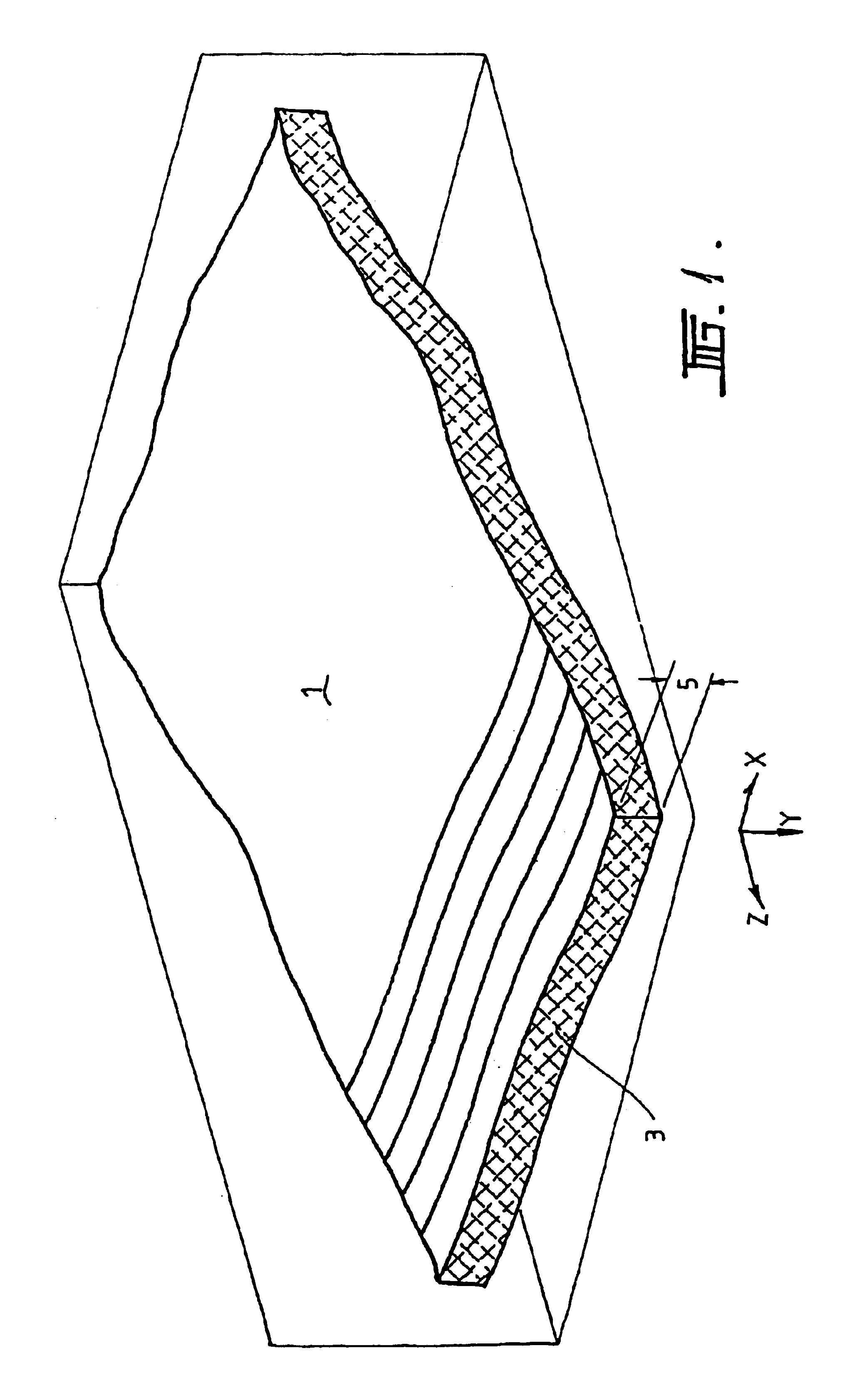
Referring firstly to FIG. 1 there is shown a seam 1 of coal relative to X, Y, and Z planes. FIG. 1 is diagrammatic and shows an upward inclination of the seam 1 together with folds and contours throughout the seam 1. The strata below and above the seam has not been shown. The seam 1 has a longwall face 3 and a vertical depth or thickness indicated by thickness 5. The depth or thickness 5 is typically, substantially uniform throughout the whole of the seam 1.

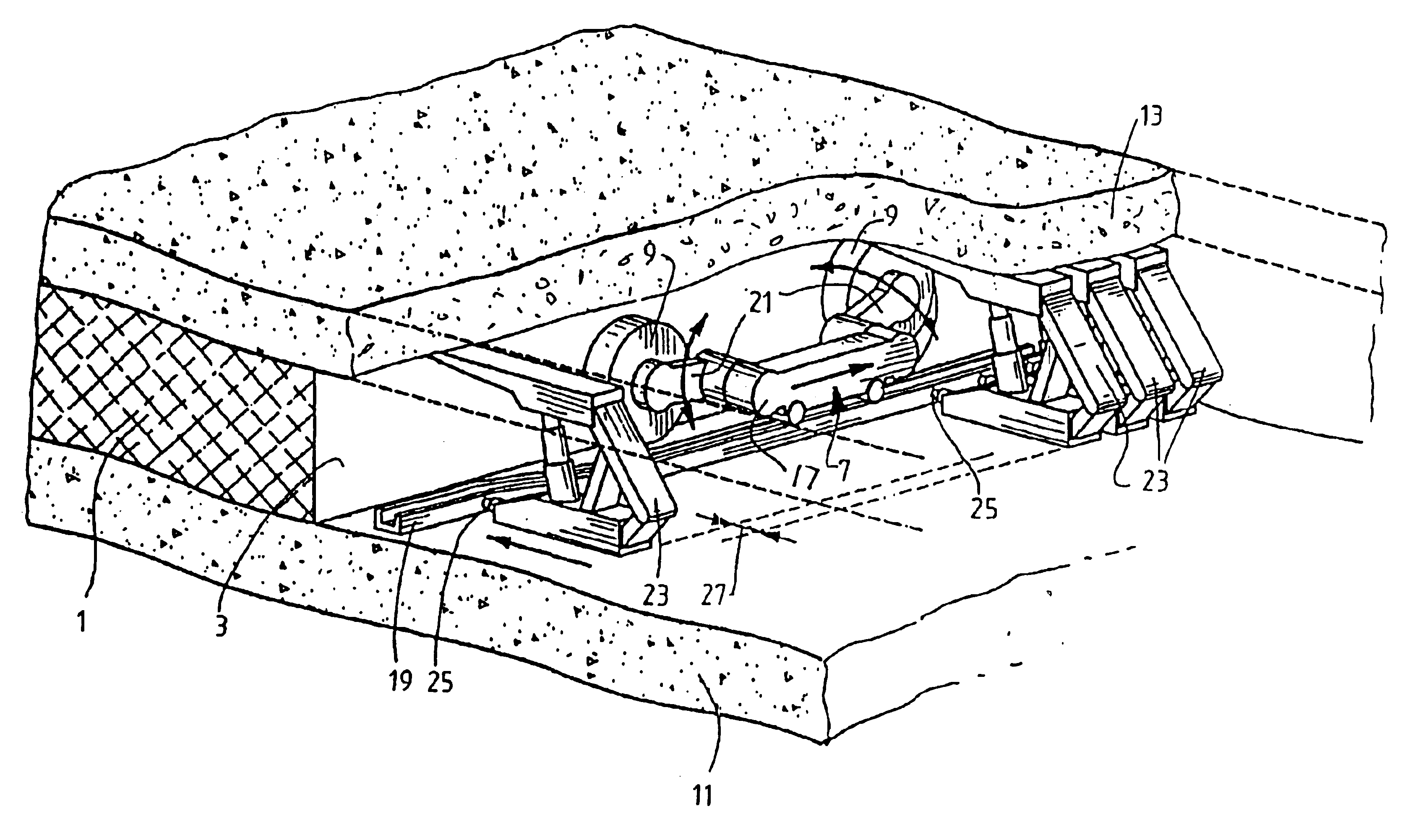
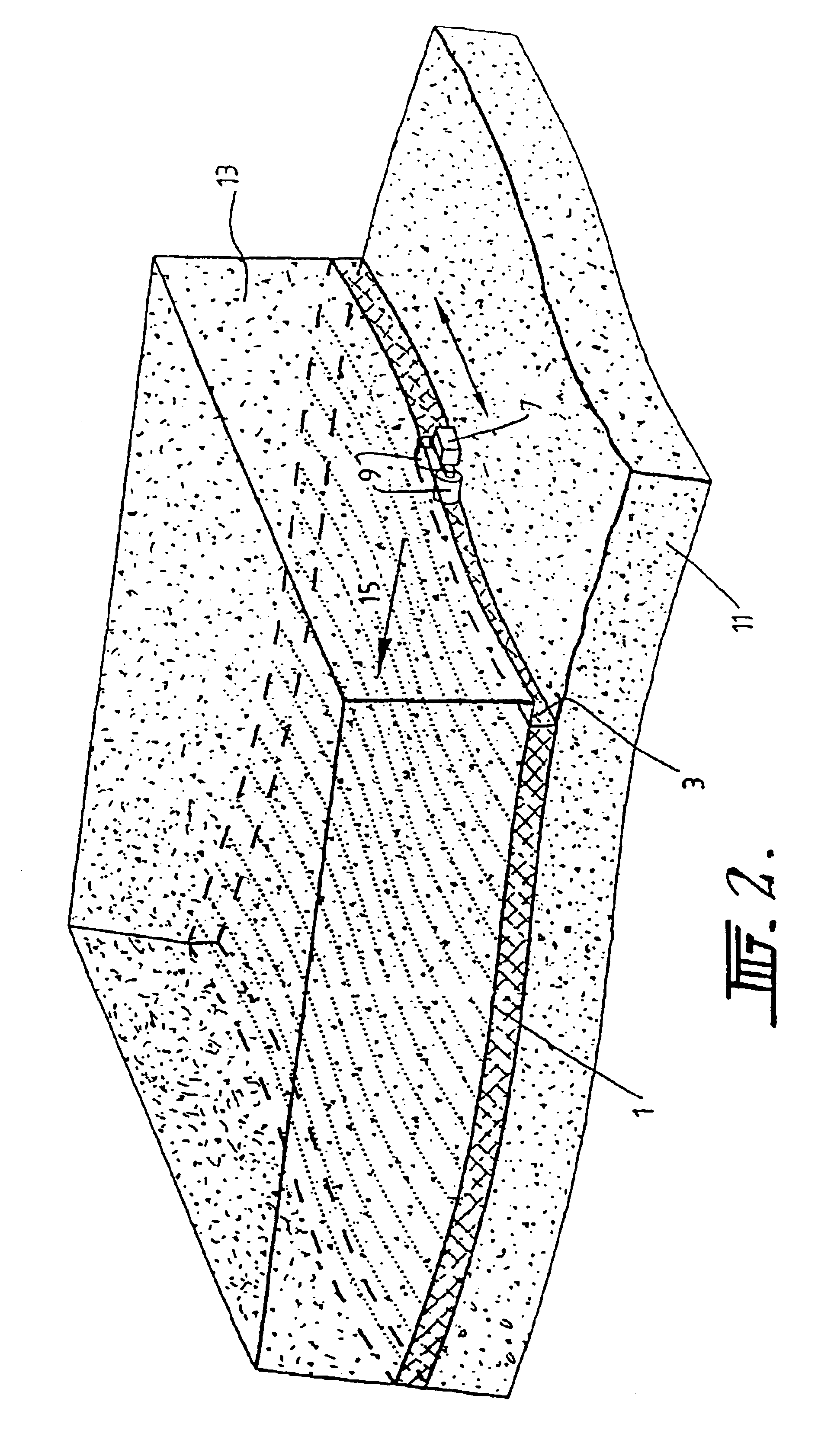
When mining the seam 1, a mining machine attempts to make a series of side-to-side cuts across the seam. Each cut is represented by the narrow line markings across the seam 1. In other words, the longwall face 3 is exposed progressively with each succeeding side-to-side cut. It can be seen that as the side-to-side cuts progress in a direction generally orthogonal to the longwall face 3 (ie in the Z direction) the horizon aspect changes upwardly. This is merely exemplary as in other examples, the horizon aspect may extend downward...


PUM


Abstract

A control system for a mining machine which moves in passes across a seam to be mined using absolute coordinates is disclosed. The machine is carried on rail and co-ordinates of the rail are measured along the length of rail. The rail is then moved to a new position for a next pass, and the distance of moving is determined from the co-ordinates previously measured. By knowing the co-ordinates, the rail can be moved to assume a desired profile, so that a desired profile of the seam can be achieved on the next pass. Co-ordinates of the up and down movement of a shearing head can also be measured and stored with the co-ordinates along the rail to provide a profile of the seam being cut, and so that on a next pass the intended position of the shearing head can be predicted and moved accordingly.

Description

FIELD OF THE INVENTIONThis invention relates to a mining machine and method whereby a mining machine can be controlled to move across a seam containing product to be mined. The invention has particular, although not exclusive application, in the longwall mining of coal.DESCRIPTION OF PRIOR ARTIn the mining of coal, processes have been developed which are referred to as longwall mining processes. In these processes a movable rail is placed to span across a coal seam. A mining machine is provided with a shearing head and the mining machine is moved to traverse along the rail from side-to-side of the seam, and the shearing head is manipulated upwardly and downwardly to shear coal from the face of the seam. Throughout each pass, the rail is moved forwardly toward the seam behind the path of the mining machine. The mining machine is then caused to traverse the seam in the opposite direction whilst the shearing head is manipulated upwardly and downwardly to remove further coal from the se...

Claims


Application Information

Patent Timeline
Patent Type & Authority Patents(United States)
IPC IPC(8): E21C35/08E21D23/14E21C35/00E21C35/24E21D23/00E21C25/06E21C35/10E21C41/18
CPCE21C35/08E21D23/14E21C35/24E21C35/10
Inventor HAINSWORTH, DAVID WILLIAMREID, DAVID CHARLES
Owner COMMONWEALTH SCI & IND RES ORG
Why Eureka
Try Eureka