Axial compressor disk for a turbomachine with centripetal air bleed

a compressor disk and turbomachine technology, applied in liquid fuel engines, vessel construction, marine propulsion, etc., can solve the problems of difficult and expensive operation, laborious piercing of the orifice, and difficult to monitor the walls of the channels, so as to facilitate the machining of the walls and the inspection of the machined walls.

Inactive Publication Date: 2005-02-22
SN DETUDE & DE CONSTR DE MOTEURS DAVIATION S N E C M A
View PDF6 Cites 27 Cited by
  • Summary
  • Abstract
  • Description
  • Claims
  • Application Information

AI Technical Summary

Benefits of technology

The object of the invention is to propose a compressor disk as mentioned in the introduction in which the machining of the walls and the inspection of the machined walls are made easier, while retaining substantially the same bleed capacities concerning pressure, flow rate, and temperatures.

Problems solved by technology

The channels are made by electroerosion, which is an operation that is difficult and expensive.
In addition, it is difficult to monitor the walls of the channels.
Piercing those orifices is likewise laborious.

Method used


Image

  • Axial compressor disk for a turbomachine with centripetal air bleed
  • Axial compressor disk for a turbomachine with centripetal air bleed
  • Axial compressor disk for a turbomachine with centripetal air bleed

Examples


Embodiment Construction

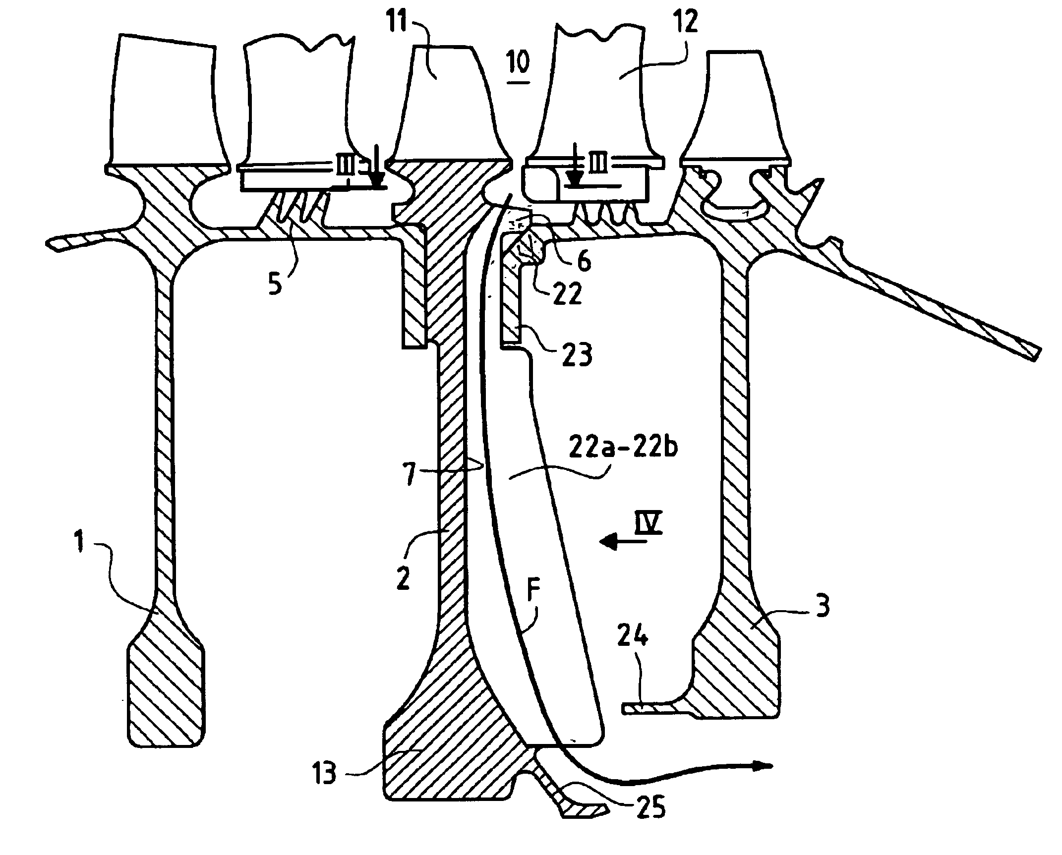
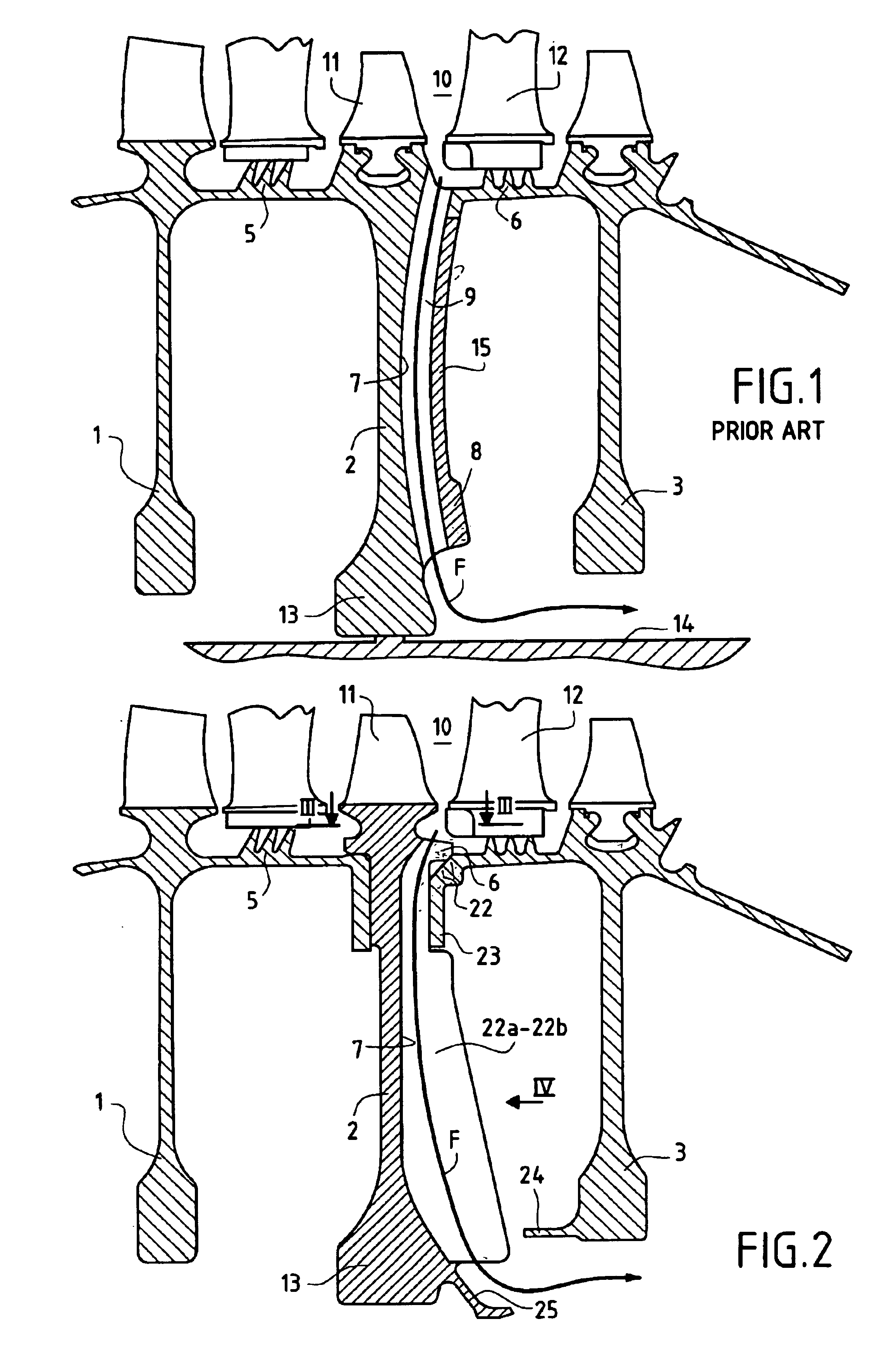
FIG. 1 shows the disks 1, 2, and 3 of three consecutive stages of a prior art turbomachine compressor. The disks 1 to 3 are interconnected by downstream flanges 5 and 6 welded to circular bearing surfaces of the upstream disk.

On its downstream face 7, the disk 2 has extra radial thicknesses 8 separated by recesses and disposed outside the working section of the disk 2. The term “working section” is used to mean the section of the disk designed in terms of materials strength to withstand the forces that apply in rotation under operating conditions of the turbomachine.

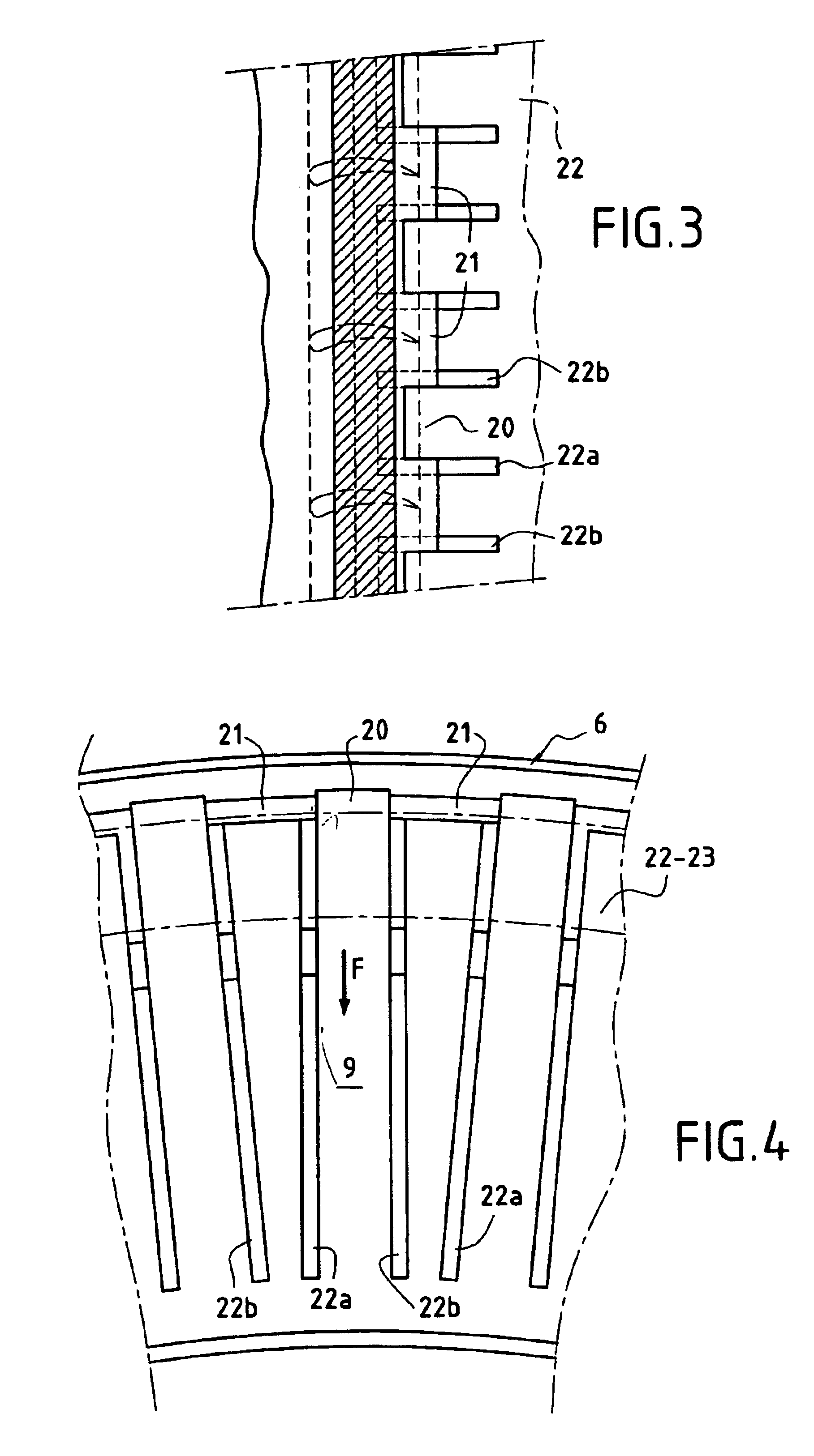
Bleed channels 9 are formed in the extra thicknesses 8. These bleed channels 9 open out through the flange 6 into the stream 10 of the hot flow between the blades 11 of the disk 2 and the vanes 12 of the stator. The air flow F bled off via a bleed channel 9 flows towards the radially inner solid portion 13 of the disk 2 and is then channeled axially by the turbine shaft 14 towards the turbines for cooling.

The bleed chann...


PUM


Abstract

The invention relates to an axial compressor disk for a turbomachine, the disk including a bleed system for bleeding air centripetally from the compressor stream in order to cool a turbine, said bleed system comprising channels formed outside the working section of the disk and parallel to said section in an extra thickness projecting away from said working section on a face of said disk, wherein the bleed channels are axially open over substantially their entire radial extent.

Description

The invention relates to an axial compressor disk for a turbomachine, the disk including a bleed system for centripetally bleeding air from the compressor stream in order to cool a turbine, the bleed system comprising channels formed outside the working section of the disk and parallel to said section in an extra thickness that projects outside said working section on a face of said disk, said channels being open to the compressor stream through a connection flange for connecting said disk to an adjacent disk.BACKGROUND OF THE INVENTIONIn order to avoid weakening the strength of the working section of the disk, FR 2 614 654 proposes piercing channels in extra thicknesses that project outside the working section of the disk, these channels passing through the flange connecting with an adjacent disk of the compressor.The channels are made by electroerosion, which is an operation that is difficult and expensive. In addition, it is difficult to monitor the walls of the channels.The stat...

Claims


Application Information

Patent Timeline
Patent Type & Authority Patents(United States)
IPC IPC(8): F04D27/02F01D5/02F01D5/08F04D29/32
CPCF01D5/082F04D29/321F04D27/0215F01D5/087Y02T50/60
Inventor AVIGNON, PHILIPPEBRUNET, ANTOINE ROBERT ALAINPASQUIS, PATRICK CLAUDE
Owner SN DETUDE & DE CONSTR DE MOTEURS DAVIATION S N E C M A
Why Eureka
Try Eureka