
Retractable antenna module

a technology of antenna module and antenna body, which is applied in the direction of collapsible antenna means, flexible/turnable line connectors, and quick-releasable antenna elements, etc., can solve the problems of high production cost and inconvenience, and achieve the effect of reliable antenna modul

Inactive Publication Date: 2005-02-22
FIH (HONG KONG) LTD
View PDF8 Cites 12 Cited by
  • Summary
  • Abstract
  • Description
  • Claims
  • Application Information

AI Technical Summary

Benefits of technology

"The present invention provides a reliable and easy-to-use antenna module for mobile phones that can be extended or retracted with one hand. The antenna module has a simple structure and includes an antenna, an elastic element, and a feed mechanism. The elastic element surrounds the lower part of the antenna and exerts an outward force against it. The feed mechanism has a connecting means and a groove, which allows the antenna to move between an extended position and a retracted position as regulated by the engagement between the connecting means and the groove and as aided by the resilience of the elastic element."

Problems solved by technology

This locking means, however, requires use of magnetic elements, and thus the antenna assembly is complex, the production costs are relatively high, and the magnetic elements influence the received signals.
Furthermore, pulling out the first extendable antenna from the retracted position to the extended position requires two hands operating together, which is not convenient.

Method used


Image

  • Retractable antenna module
  • Retractable antenna module
  • Retractable antenna module

Examples


Embodiment Construction

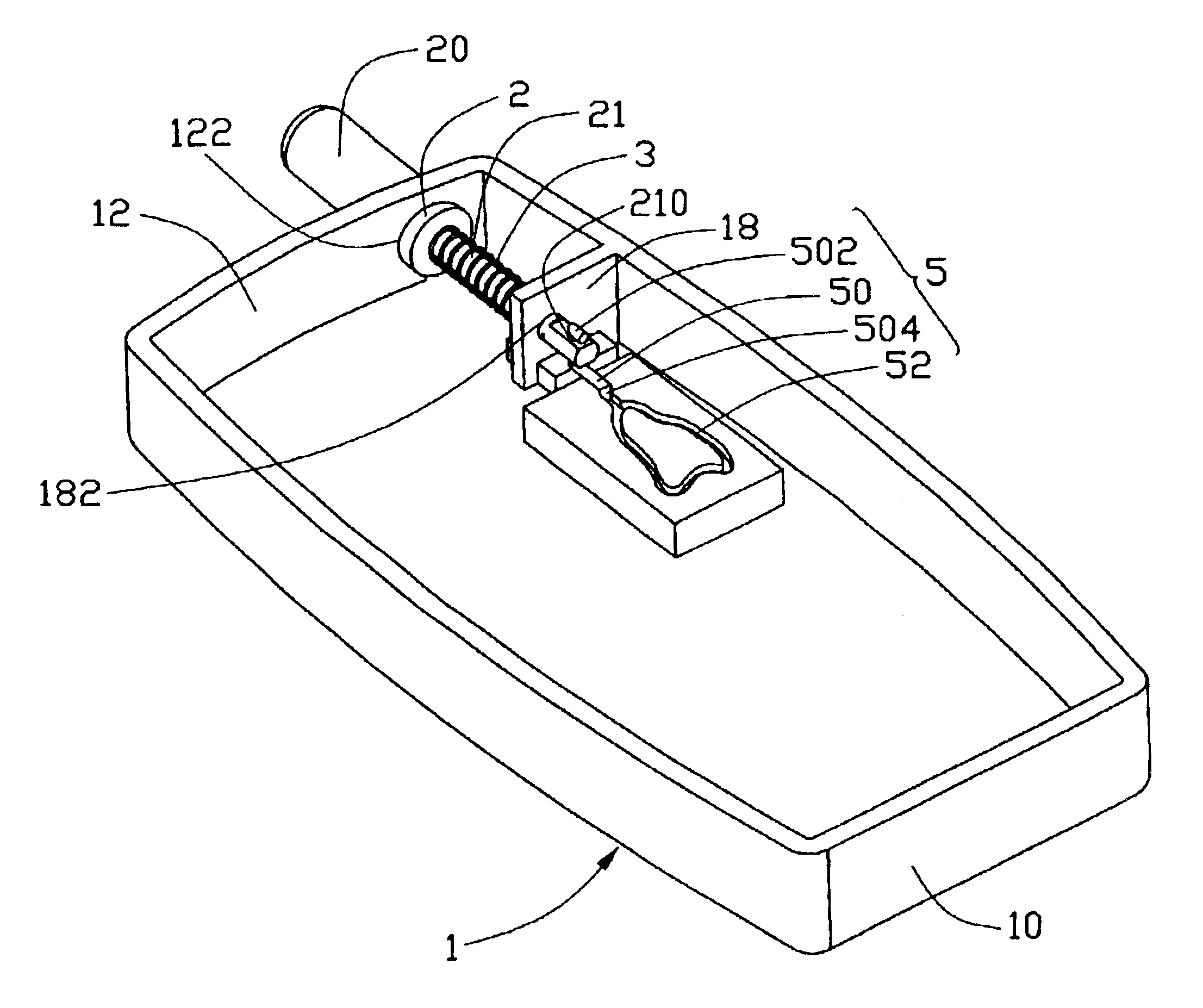
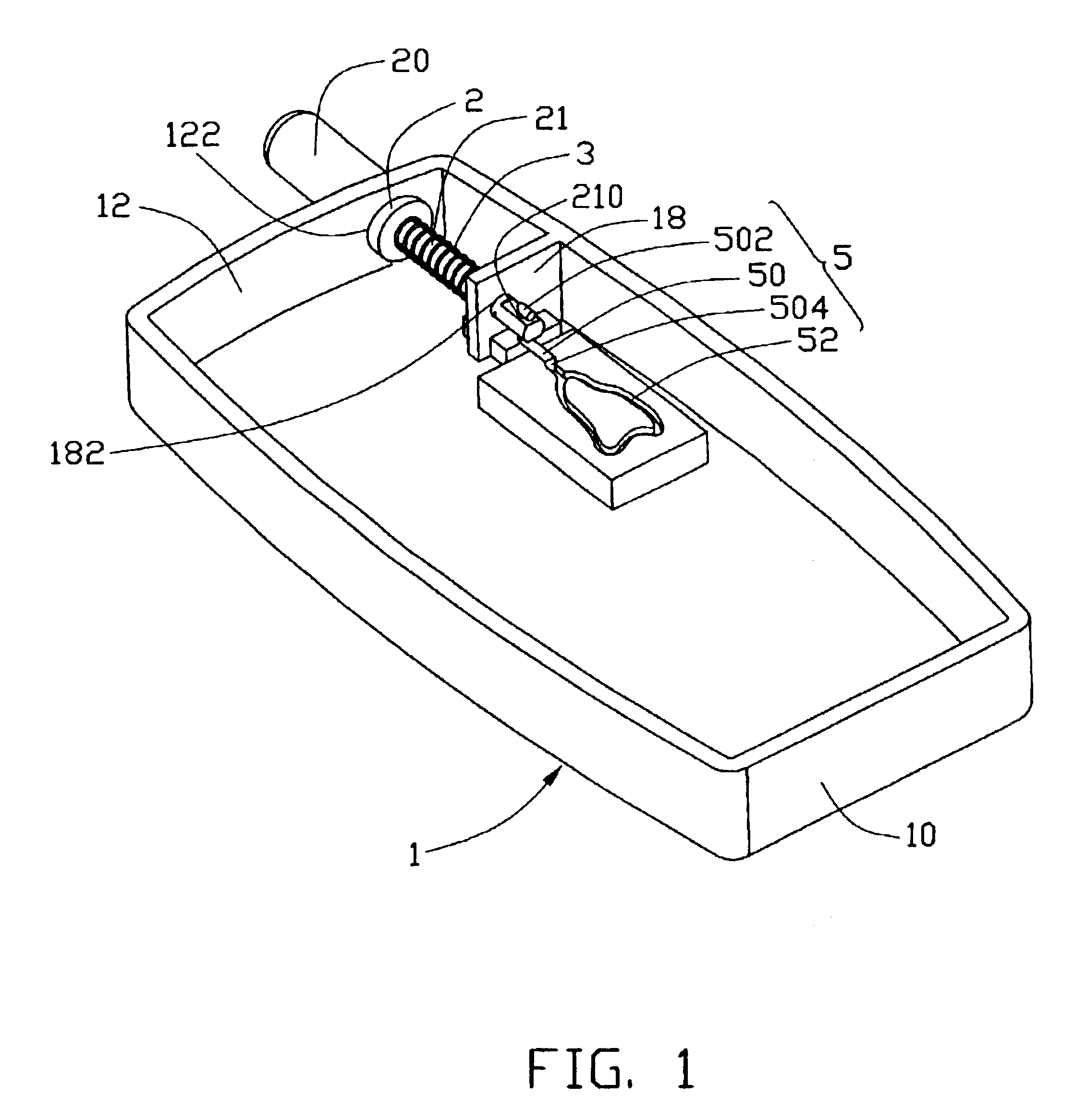
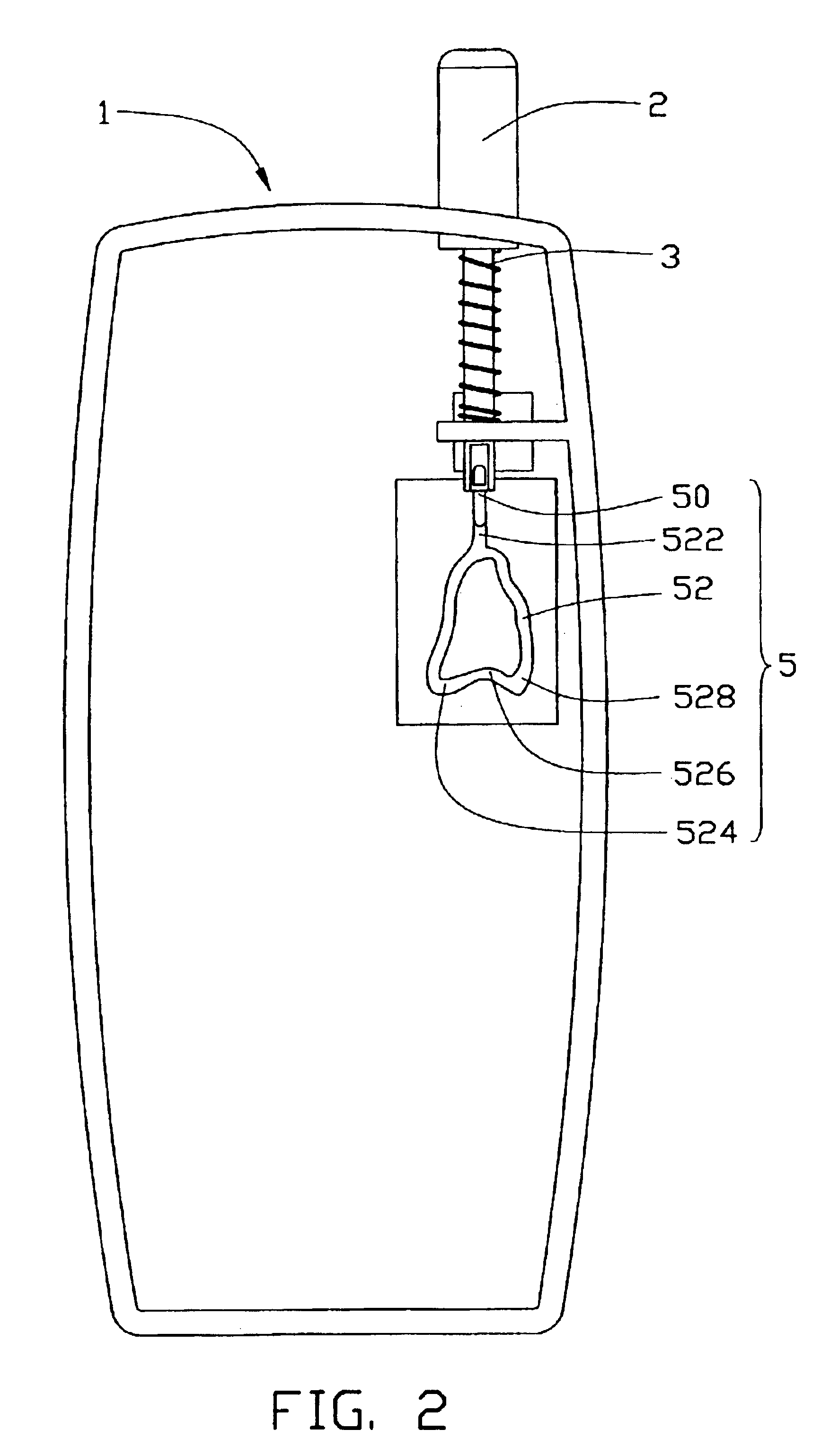
Referring now to the drawings in detail, FIGS. 1 to 5 show an antenna module 1 for a mobile phone in accordance with the first preferred embodiment of the present invention. The antenna module 1 (see FIG. 1) includes a housing 10, an antenna 2, an elastic element 3 and a feed mechanism 5. The housing 10 has a top surface 12, in which a first support opening 122 is defined. A first support plate 18 extends from a sidewall of the housing 10 and defines a second support opening 182 aligned with the first support opening 122. The antenna 2, which can move between an extended position and a retracted position, comprises an upper part 20 and a lower part 21. The upper part 20 and the lower part 21 are both circular, and are covered with plastic for insulating and protecting the antenna 2 from damage. The diameter of the upper part 20 is larger than that of the lower part 21. A hole 210 is defined through the lower part 21 of the antenna 2. The feed mechanism 5 includes a connecting means ...


PUM


Abstract

An antenna module (1) for a mobile phone in accordance with the present invention includes an antenna (2), an elastic element (3) and a feed mechanism (5). The elastic element surrounds a lower part (21) of the antenna and pushes the antenna outwardly. The feed mechanism has a connecting means (50) and a guiding groove (52). The connecting means movably engages with the antenna and slidably engages with the groove. The movement of the antenna between an extended position and a retracted position is regulated by engagement between the connecting means and the groove, and is aided by the resilience of the elastic element. A user can move the antenna between a retracted position and an extended position using one hand.

Description

FIELD OF THE INVENTIONThe present invention relates to an antenna module, and particularly to a retractable antenna module for an electronic device.BACKGROUND OF THE INVENTIONIn recent years, particularly given the trend toward miniaturization in mobile phones, antennas of mobile phones are being designed to be retractable. One such antenna is disclosed in U.S. Pat. No. 5,710,567. Referring to this patent, the antenna device comprises a first extendable antenna and a second antenna. The first extendable antenna is movable between an extended position, where it switches on, and a retracted position, where it switches off. The first extendable antenna has a first holding device on its lower portion which cooperates with a second holding device arranged on a guide for the first extendable antenna. The holding devices cooperate to releasably lock the first extendable antenna in the extended position. The first and second holding devices comprise mutually and magnetically attractive elem...

Claims


Application Information

Patent Timeline
Patent Type & Authority Patents(United States)
IPC IPC(8): H01R35/00H01Q1/24H01Q1/08H01R35/04
CPCH01Q1/088H01R35/04H01Q1/244H01R2201/02H01R2201/16
Inventor CHANG, SULI
Owner FIH (HONG KONG) LTD
Learn More