Enhanced ratio control to establish CVT ratio with excellent precision

a technology of enhanced ratio and precision, applied in the direction of instruments, mechanical equipment, gearing, etc., can solve the problems of unresolved noise problem, inability to find cvt ratio, and inability to accurately determine the value of cvt ratio,

Inactive Publication Date: 2005-02-22
NISSAN MOTOR CO LTD
View PDF14 Cites 93 Cited by
  • Summary
  • Abstract
  • Description
  • Claims
  • Application Information

AI Technical Summary

Problems solved by technology

In CVTs, a measured value of CVT involves noise, which may cause hunting in CVT ratio.
The measured value of CVT ratio inevitably involves noise because trains of output pulses of revolution speed sensors are used in calculating a ratio between a revolution speed of a CVT input member and a revolution speed of a CVT output member.
This noise problem has not been solved by the prior art because the width of a dead zone is controlled in an open loop manner.
The width of the dead zone is difficult to nicely fit all noise situations derived from difference in the width of noise from one unit to another.
As shown in FIG. 26B, the dead zone is exceeded, causing hunting of actuator command that leads to undesired pulsating ratio change.
a) Due to hunting or standing wave, a CVT cannot always establish, with good precision, a predetermined value of CVT ratio required for moving the vehicle from standstill.
In this case, the driver feels unpleasantly a difference in vehicle acceleration upon starting the vehicle.
However, so extending the usable range of CVT ratios requires an increase in size of a CVT unit to provide the margins, pushing up manufacturing cost.
If such increase in size of a CVT unit is not desired, one cannot accomplish an improvement in fuel economy as high as expected.
c) Difficulty in establishing, with good precision, a desired value of CVT ratio makes it difficult for an infinitely variable transmission (IVT) to have a geared neutral point (GNP).

Method used


Image

  • Enhanced ratio control to establish CVT ratio with excellent precision
  • Enhanced ratio control to establish CVT ratio with excellent precision
  • Enhanced ratio control to establish CVT ratio with excellent precision

Examples


Embodiment Construction

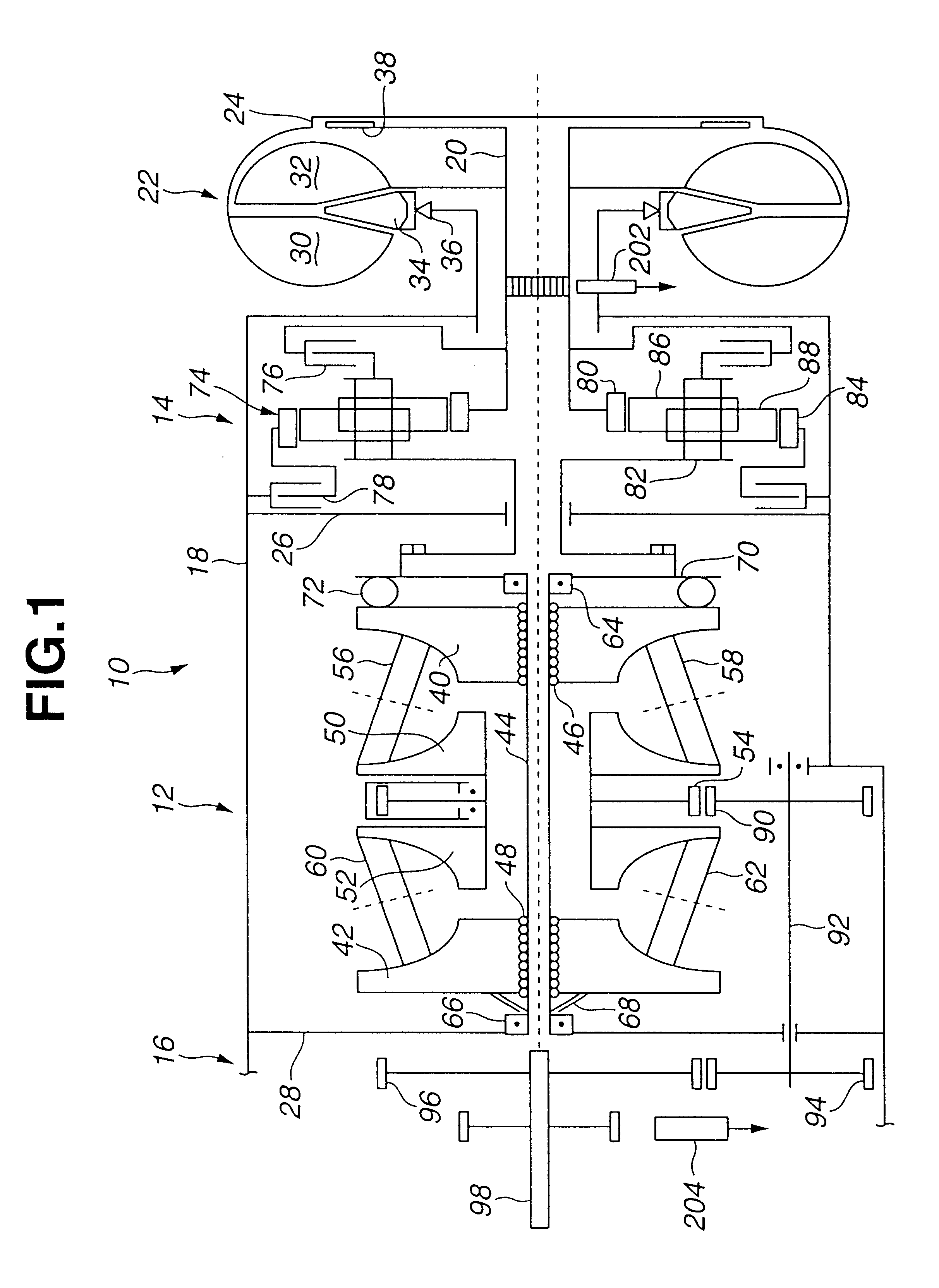
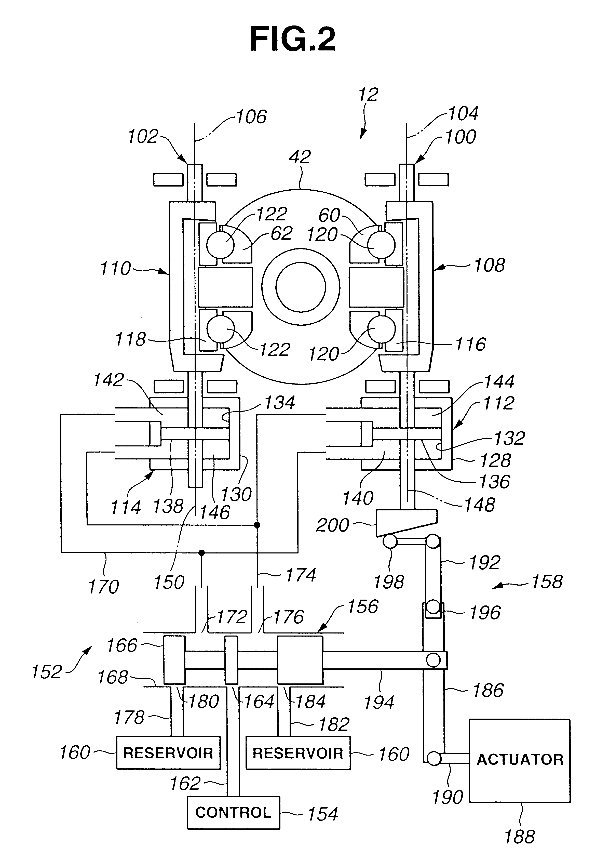
Referring to FIGS. 1 and 2, a CVT 10 includes a dual cavity toroidal drive 12 coaxially connected to a forward positioned input gear section 14 and connected also to a rearward positioned output gear section 16. For purpose of clarification, the terms front or forward refer to the right side, and rear or rearward refer to the left side of the view shown in FIG. 1. All three elements 12, 14 and 16 are enclosed in a housing 18 and driven by an input or turbine shaft 20 that is powered by an engine (not shown) through a torque converter 22 or a lock-up clutch 24. Housing 18 has three chambers, one for each element 12 ,14 and 16, separated by walls 26 and 28. Torque converter 22 is a conventional torque converter including a pump impeller 30 connected to the engine, a turbine runner 32 connected to input shaft 20, and a stator 34 grounded via a one-way brake 36. Lock-up clutch 24 is a conventional lock-up clutch including a clutch element 38 connected to input shaft 20.

Dual cavity toroi...


PUM


Abstract

A system for enhanced ratio control in a continuously variable transmission (CVT) includes a ratio control element positionable by an actuator in response to an actuator command to establish various CVT ratios in the CVT. At least one sensor generates a train of pulses indicative of speed of rotation of a predetermined rotary member of the CVT. A measured CVT ratio generator derives information of an actual CVT ratio out of at least the train of pulses to give a measured value of CVT ratio. A filter processes the measured value of CVT ratio in a manner to refine the information of the actual CVT ratio to give an estimated value of CVT ratio. A command generator determines the actuator command such that the actuator command remains unaltered when a deviation of the estimated value of CVT ratio from a desired value of CVT ratio stays within a dead zone. A filter and command generator manager narrows the dead zone to meet precision requirement upon determination that the desired value of CVT ratio has been accomplished and adjusts filter gain at the filter in a manner to keep amplitude at frequency of noise that is contained in the measured value of CVT ratio within the narrowed dead zone.

Description

BACKGROUND OF THE INVENTION1. Field of the InventionThe present invention relates to a method and a system for enhanced ratio control in a continuously variable transmission.2. Description of the Background ArtContinuously variable transmissions (CVT's) are transmissions that change a speed ratio continuously, not in discrete intervals. This continuous nature of CVT's gives them an infinite number of speed ratios, making them very attractive for automotive use.Various types of CVT are known. One such example is a CVT with pulley / V-belt power transfer. Another example is a CVT with disc / roller power transfer. The CVT of this type is often referred to as a toroidal-type CVT (TCVT) because it transmits torque from one rotating semi-toroidal disc to another semi-toroidal disc by traction rollers through a traction force. The two semi-toroidal discs form a toroidal cavity. In each toroidal cavity, it is preferred to have two traction rollers in equiangularly spaced relationship engaging ...

Claims


Application Information

Patent Timeline
Patent Type & Authority Patents(United States)
IPC IPC(8): F16H61/662F16H61/66F16H37/08F16H61/10
CPCF16H61/6648F16H37/086Y10T477/6242Y10T477/619
Inventor JOE, SHINICHIROKAWABE, TAKETOSHIMENSLER, MICHEL
Owner NISSAN MOTOR CO LTD
Why Eureka
Try Eureka