Shear-locking device

a technology of locking device and shear, which is applied in the direction of cutting tools, metal working apparatus, cutters, etc., can solve the problems of not being able to guarantee closure and being regarded as a defect by users, and achieve the effect of easy attraction of dir

Inactive Publication Date: 2005-03-01
WOLF GERATE GMBH
View PDF19 Cites 14 Cited by
  • Summary
  • Abstract
  • Description
  • Claims
  • Application Information

AI Technical Summary

Benefits of technology

The tumbler plate can be pivoted by a projection projecting beyond the handle shell. However, this would result in uncomfortable handling. According to a further refinement of the invention, a slide button which, instead of a rotary motion, describes a linear motion on the outside of the handle shell of one limb of the shears should therefore be provided for ergonomic reasons. According to the preferred exemplary embodiment of the invention, this slide button is arranged in such a way that it can be operated in a one-handed manner with the thumb of the right or left hand with which the shears are being grasped. The connection between the tumbler plate and the slide button is made by means of a pin, which is fixed by frictional engagement in a hole in the tumbler plate and engages in a guide slot in the form of an elongate hole in the slide button in such a way that the stroke motion of the pin is accommodated. The slide button can be guided in a guide track in the handle shell in a form-locking manner i.e., held together due to their respective shapes. This avoids a gap between the button and the guide track, which could easily attract dirt, which could in turn lead to jamming of the tumbler mechanism.
The slide button can be fixed by frictional engagement in the respective closed position of the shears, the self-locking of the locking elements excluding unwanted opening under the action of the opening spring. According to a preferred embodiment of the invention, however, a latching mechanism in the form of a precision latching structure is provided, thereby making it possible to fix the slide button in defined precision-matched positions relative to the handle shell guiding it. The latching arrangement is of resilient design, with the result that it is always possible to ensure latching in the end position.

Problems solved by technology

Tolerance variations during manufacture and wear on the shears which occurs during use often lead to the appearance of a parallel or wedge-shaped light gap in the closed position and, although this does not necessarily impair the cutting performance of the shears, it is often regarded as a defect by the user.
The customary shear-locking devices with tumblers which are fixed in a very specific latching position cannot guarantee closure without a light gap in the manner described.

Method used


Image

  • Shear-locking device
  • Shear-locking device
  • Shear-locking device

Examples


Embodiment Construction

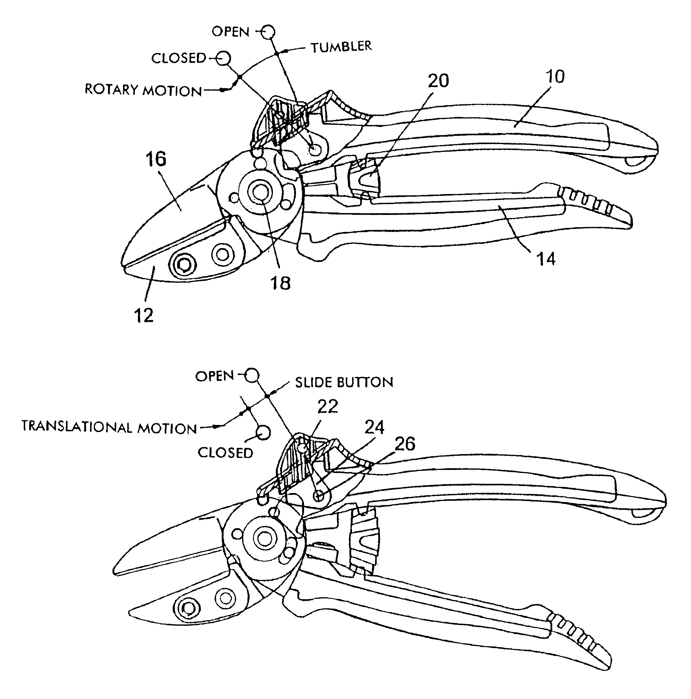
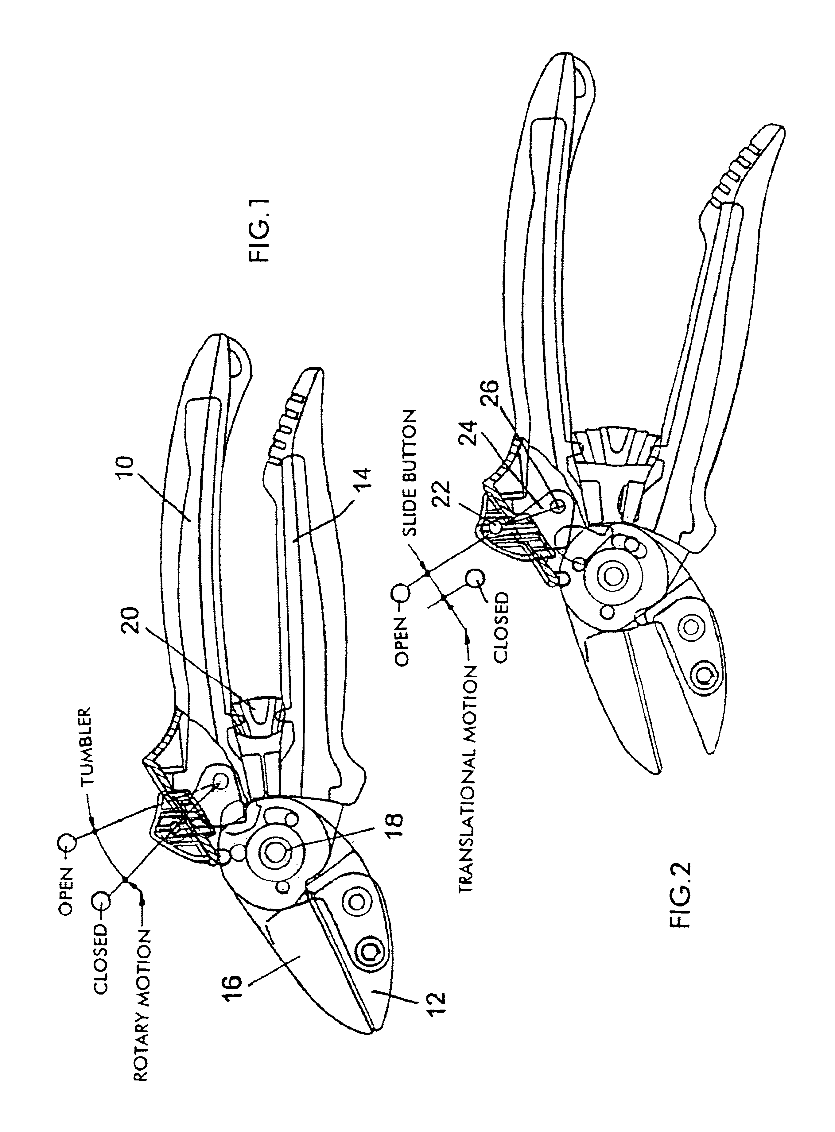
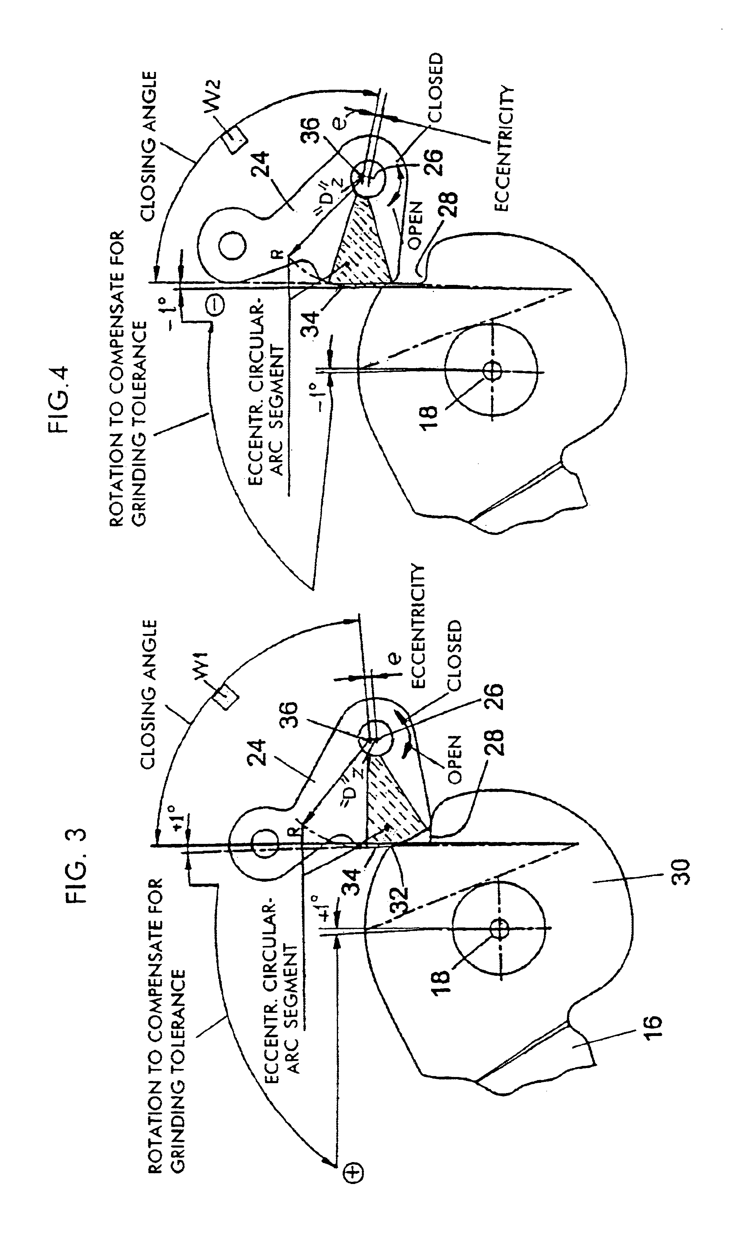
The anvil shears illustrated in FIGS. 1 and 2 have a first limb 10 with an anvil 12, arranged adjustably thereon, and a second limb 14 with a blade 16 which interacts with the anvil. The two limbs 10 and 14 of the shears are connected to one another by a hinge pin 18. An opening spring 20 arranged between the limbs 10 and 14 attempts to spread the limbs 10 and 14 apart. The shears are held in the closed position against the force of the opening spring 20 by a locking device described in detail below. This locking device has a slide button 22, which pivots a tumbler plate 24 about an axis 26. This tumbler plate interacts with a catch recess 28 in the blade 16, as can be seen most clearly from FIGS. 3 and 4. The blade 16 is mounted by its rear part 30 on the hinge pin 18, and this part 30 is riveted to the front portion of the limb 14 of the shears. This part 30 of the blade 16 bears the catch recess, which has a rounded cam surface 32 that interacts with a latching cam surface 34 of ...


PUM


Abstract

Shears having a locking mechanism which ensures self-locking closure without any light gap. A tumbler (24) on one limb of the shears pivoted by a slide button (22) has a cam surface (34) interacting in a self-locking manner with a catch groove (28) on a cam surface (32) on the other limb (14). The catch groove (28) can have a larger configuration in the direction of closure. An arched cam surface may also be provided, which is eccentrically located in relation to the pivoting axis of the tumbler. A fine locking device (50) for the slide button may be provided so the slide button can be fixed in different closed positions to prevent unintentional closure in the open position.

Description

BACKGROUND OF THE INVENTIONThe invention relates to pruning shears having a locking device including manually actuated slide button and a tumbler which is actuated by the latter and locks the limbs of the shears in the closed position against the force of an opening spring.SUMMARY OF THE INVENTIONLocking devices of this kind are generally used to protect the shears from being opened unintentionally when not in use and to a large extent avoiding any risk of injury. The smaller space requirements when they are closed makes them easier to handle, store and transport. The locked position is at the same time the standby position, in which the handles of the shears can be grasped comfortably with one hand so that the shears can be held ready for cutting once the interlock has been released, which it should be possible to do with the same hand.These requirements are generally met if the two tips of the limbs of the shears rest against one another in the closed state and the handle shells c...

Claims


Application Information

Patent Timeline
Patent Type & Authority Patents(United States)
IPC IPC(8): A01G3/00A01G3/02
CPCA01G3/02
Inventor SCHNEIDER, MANFREDSTAUDT, GERHARD
Owner WOLF GERATE GMBH
Why Eureka
Try Eureka